There were two sets of Tips, onshore and offshore, corresponding with the two markets Vulcan sold and serviced its products into. The Vulcan Offshore Tips have been on this site and its predecessors since 1998; it is appropriate that these appeared on the tenth anniversary of that posting. In the case where the specific onshore tip has an offshore counterpart, we’ve linked to the offshore tip. In cases where we’ve covered the same information in other ways, we’ve linked to that too.
Many tips refer to factory parts and service. Obviously these are no longer available, but there are sources for most of what is contained in these tips.
As is the case with the offshore tips, we’ve added commentary where appropriate. We also strongly recommend that you acquire the Vulcan Hammer Guide to Pile Driving Equipment for more information and several field service manuals for Vulcan hammers. Some of the tips are covered in that volume and are linked appropriately.
TIP # 001 : HEAD GASKET/SINGLE ACTING HAMMER
We have noticed over the years that some hammer users do not replace a leaking Cylinder Head Gasket on Single Acting Hammers. They do this on the assumption that it really isn't necessary because a Single Acting Hammer does not have pressure between...
Read More
Tip #001: HEAD GASKET/SINGLE ACTING HAMMER
 We have noticed over the years that some hammer users do not replace a leaking Cylinder Head Gasket on Single Acting Hammers. They do this on the assumption that it really isn’t necessary because a Single Acting Hammer does not have pressure between the Cylinder Head and the Piston. It is true that on Single Acting Hammers air or steam is not directed into this area as is done on Differential Hammers. But when the Piston of a Single Acting Hammer Is on the upstroke the Piston travels up past the Exhaust Ports and traps air between the Cylinder Head and the Piston. This trapped air acts as a cushion to slow up and stop the upward travel of the Piston and Ram. Without the Cylinder Head Gasket the trapped air will escape and the Piston will strike the Cylinder Heed. Eventually this pounding will lengthen or strip the threads of the Cylinder Head Studs. This will allow more air to escape until the Piston will strike the Cylinder Head on every stroke and will break the Cylinder Studs and tear the Cylinder Head completely from the Hammer.
TIP # 002 : CHECKING SLIDE BAR
A quick way to check the correct position of the slide bar is shown in the drawing and picture above. Place a straightedge across the machined boss area of the Ram as shown in the picture. The lower edge of the straightedge should be even with the...
Read More
Tip #002: CHECKING SLIDE BAR
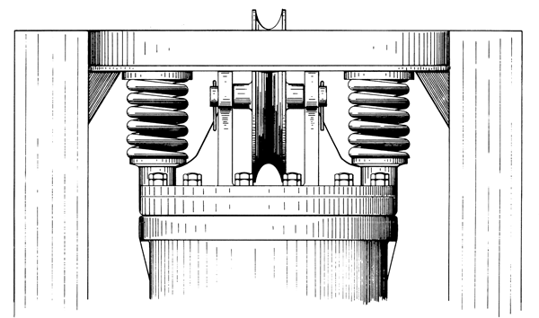
 A quick way to check the correct position of the slide bar is shown in the drawing and picture above.
Place a straightedge across the machined boss area of the Ram as shown in the picture. The lower edge of the straightedge should be even with the “break” of the round stock of the slide bar as circled in the drawing.
Note: strictly speaking, this only applied to hammers of the “020” series or smaller. Hammers larger than this have a gap between the straight edge and the slide bar break. Details on this are available in the Vulcanhammer Guide to Pile Driving Equipment.
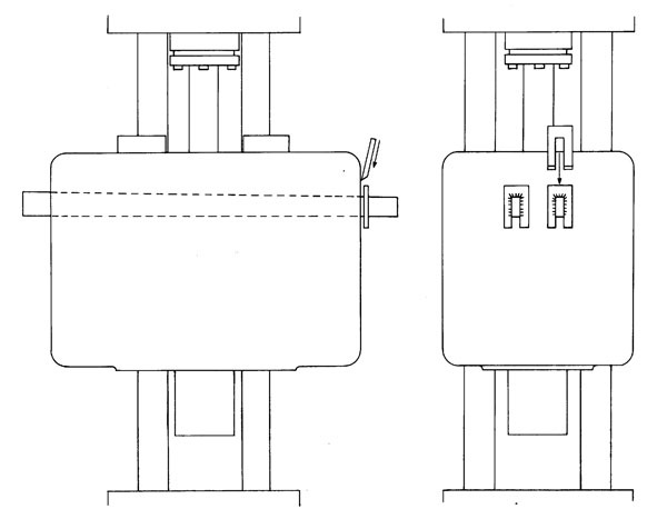
TIP # 003 : VALVE FLUTTER
Under certain atmospheric conditions, a film of ice will form on the inside wall of the steam chest. This film prevents the valve from seating properly and also reduces friction between the valve and steam chest wall. In some driving conditions, this...
Read More
Tip #003: VALVE FLUTTER
 Under certain atmospheric conditions, a film of ice will form on the inside wall of the steam chest. This film prevents the valve from seating properly and also reduces friction between the valve and steam chest wall. In some driving conditions, this lack of friction will allow the valve to “bounce” or “flutter,” needless to say, causing poor performance of the hammer. A quick remedy is the spring arrangement shown in the drawings above left. The spring holds the trip over center as it rotates. A permanent solution to flutter is shown in the drawing above right. This drawing is of the new type trip and open steam chest head equipped with a detent spring.
TIP # 004 : REDUCED HAMMER ENERGY
Vulcan Hammer Guide to Pile Driving Equipment...
Read More
TIP # 005 : LUBRICATION
Below are the lubrication specifications for the Vulcan offshore pile hammers. Below is a hammer diagram showing the locations of lubricant applications. APPLICATION POINT Lube Type Oil Viscosity Flash Point (Min.) Other Requirements...
Read More
Tip #005: LUBRICATION
Below are the lubrication specifications for the Vulcan offshore pile hammers. Below is a hammer diagram showing the locations of lubricant applications.
APPLICATION POINT
|
Lube Type
|
Oil Viscosity
|
Flash Point (Min.)
|
Other Requirements
|
SUS, 212° F
|
cSt, 100°C
|
Deg. F
|
Deg. C
|
- Cylinder and Base Jaws.
- Trip Faces.
- Slide Bar.
- Slide Bar Dovetail.
- Columns/Ram Grease fittings
- Columns/Exposed Surfaces
- Hydra/Nuts
|
NLGI EP2 Grease
|
70-100
|
13-20
|
450
|
235
|
- Permitted Thickners
- Lithium 12 Hydroxy-Stearate
- Lithium Complex
- Calcium Complex
- Polyurea
- MoS2 Anti-Wear Additive
- Anti-Rust Additive
|
- Relief Ports (Steam Opr.)
- Steam Line Oiler
|
Steam Cylinder Oil
AGMA 8
|
160-190
|
34-41
|
550
|
290
|
10% Tallow or Lard Content
|
- Relief Ports (Air Opr.)
- Air Line Oiler
|
Air Compressor Oil
AGMA 1
|
40-50
|
40-50
|
400
|
200
|
Anti-Oxidant
|
- Outboard Bearing
- Open Steam Chest Bearing
|
Gear Oil
AGMA 5 EP
|
80-105
|
80-105
|
400
|
200
|
|
Image: Lubrication diagram
It is important to keep your Vulcan hammer properly lubricated to insure the maximum possible hammer life and driving performance.
Also, for the threads of the cable fittings. use an an anti-seize compound to prevent galIing and freezing of the threads.
*NLGI EP2 greases will vary widely in the results for this application. Another alternative to this is a heavy open gear lubricant with MoS2 anti-wear additive. This should be applied directly to the exposed columns.
TIP # 006 : KEEPING RAM KEYS TIGHT
When some hammers get enough mileage on them to warrant retirement and under certain driving conditions, the contractor may have trouble keeping the ram keys tight. Usually under these circumstances, the contractor will weld the keys to the ram and...
Read More
Tip #006: KEEPING RAM KEYS TIGHT
 When some hammers get enough mileage on them to warrant retirement and under certain driving conditions, the contractor may have trouble keeping the ram keys tight. Usually under these circumstances, the contractor will weld the keys to the ram and worry about the consequences later. The drawing above shows a better way of keeping the keys tight and allows for quick and easy re-tightening during the job.
TIP # 007 : 11 RULES FOR PILE DRIVING
The Name of the Game -- Heavier Ram - Shorter Stroke Concrete piles cracking while driving in either soft silt or very hard ground? The solution is the same for both problems: Use a thicker cushion block and a hammer with a heavier ram and shorter...
Read More
Tip #007: 11 RULES FOR PILE DRIVING
The Name of the Game — Heavier Ram – Shorter Stroke
Concrete piles cracking while driving in either soft silt or very hard ground? The solution is the same for both problems: Use a thicker cushion block and a hammer with a heavier ram and shorter stroke. The solution and others to related problems, comes from Prof. T. J. Hirsch of Texas A&M’s Texas Transportation Institute, who led a research project in the problems of cracking and spalling concrete piles. TTI is the official research agency for the state highway department. His reasoning is this: The compression wave sent down a pile by the hammer blow. rebounds back up the pile when it reaches the end – as a tension wave if the pile tip is in a soft medium that offers little resistance, and as a compression wave if the pile tip is lodged against something very firm. If the pile is long and the stress waves short, the return wave will meet the compression wave of the next hammer blow, and the two can add up to a resultant force that is destructive. A heavier ram has a longer impact time on the head of the pile. and thus produces a longer compression wave. Thicker cushioning also stretches out the impact time. Professor Hirsch sums up the fundamentals of good pile design and pile driving as follows:
- Use adequate cushioning materials between the pile driver’s steel helmet or cap and the concrete pile head. For piles under 50 ft., only 3 or 4 in. of wood cushioning material (such a green oak, gum. pine, or fir wood plywood) may be adequate if there is reasonably good point soil resistance. More wood cushioning, 6 to 8 in. or more, may be required when driving longer piles in very soft soil. The wood cushioning material should be placed on top of the pile with the grain horizontal and inspected to see that it is in good condition. When it begins to become highly compressed, charred, or burned, it should be replaced. Some specifications require a new cushion on every pile. If driving is extremely hard, the cushion may have to be replaced several times during driving of a single pile. Adequate cushioning is usually a very economical way to control driving stresses.
- Driving stresses can be reduced by using a heavy ram with a low impact velocity (short stroke) to obtain the desired driving energy rather than a light ram with a high impact velocity (large stroke). Driving stresses are proportional to the ram impact velocity.
- Reduce the ram velocity or stroke during early driving when light soil resistance is encountered. Anticipate soft driving, or at the first sign of easy driving reduce the ram velocity or stroke to avoid critical tensile stresses. This is very effective when driving long piles through very soft soil.
- If predrilling or jetting is permitted in placing the piles, be sure that the pile point is well seated with reasonable resistance at the point before full driving energy is used. Driving and jetting should not be done simultaneously.
- Be sure that the pile driving helmet or cap fits loosely around pile top so that the pile may rotate slightly without binding within the driving head to prevent torsional stress. The helmet should be centered on pile head so eccentric load will not be applied.
- The pile should be straight and not cambered because of uneven prestress or poor concrete placement during casting. High flexural stresses may result during driving of a crooked pile.
- The top of the pile must be square or perpendicular to the longitudinal axis of the pile. Eccentricity concentrates stress.
- Cut the ends of prestressing or reinforcing steel flush with the end of the pile head to prevent their direct loading by the ram stroke.
- Use adequate spiral rdnforcing at the pile head and tip to reduce the tendency of the pile to split or spall.
- Use adequate amount of prestress in prestressed piles or reinforcement in ordinary precast piles to resist reflected tensile stresses.
- Chamfer the top and bottom edges and corners of the pile to reduce the tendency of the concrete to spall.
Originally appeared in Hirsch, T.J. (1966) Construction Methods and Equipment, New York: McGraw-Hill.
The whole subject of “heavy mass-low striking velocity” is one that Vulcan dealt with throughout the entire history of the air/steam hammer line. The debate has survived the company: one competitor took space in his first online newsletter to make the following commentary on this very tip:
That was written in 1966. At the time, the air hammer was a popular tool. Then the diesel hammer took over the world, and the mighty air hammer manufacturers are a tiny fraction of what they were.
While there’s no doubt diesel hammers have been successful, the physics that Dr. Hirsch describes are still correct, but must be understood in proper context.
When steam hammers were first introduced, one of the major changes that took place was the relationship between ram weight and hammer energy. Drop hammers were inherently long-stroke hammers, and the pile top damage to the wood piles could be considerable. Shortening the stroke and increasing the ram weight reduced the peak force in the pile, and thus the driving stresses in the pile. This became more critical when concrete piles became popular, as controlling the tension cracking phenomenon Hirsch describes is critical.
Diesel hammers, to some extent, reversed the trend by reducing the ram weight and lengthening the stroke. This made for a lighter hammer, and one that didn’t require the external power source. So how to control the pile stresses? One way is to decrease the cushion stiffness, which decreases the natural frequency and increases the impact period. To some extent, the effect of shortening the stroke can be replicated in this way, but not entirely.
It’s also noteworthy that steel piling are more resistant to driving stresses. So high velocity impact is not as critical with these piles as it is with concrete piles. Vulcan recognized this fact in the development of the 560, first produced around the time this tip was issued.
However, for the driving of concrete piles, especially larger size and capacity piles, it’s still best to use a hammer with a low impact velocity and a heavy ram to limit the pile stresses, be that hammer an air/steam or hydraulic hammer.
TIP # 008 : RAM KEYS TOO TIGHT
Sometimes it is difficult not to tighten the Ram Keys too much. Driven with a heavy weight a Ram Key can easily be driven so far as to bend. Figure No.1 shows a Ram Key properly seated. Figure No.2 shows a Ram Key driven too far and bent. The key is...
Read More
Tip #008: RAM KEYS TOO TIGHT
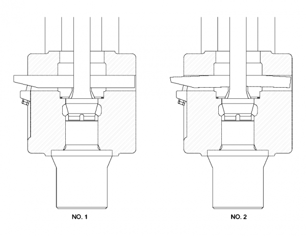 Sometimes it is difficult not to tighten the Ram Keys too much. Driven with a heavy weight a Ram Key can easily be driven so far as to bend. Figure No.1 shows a Ram Key properly seated. Figure No.2 shows a Ram Key driven too far and bent. The key is tight when it just starts to leave the seat at either end.
TIP # 009 : BLOW COUNT/ENERGY
One of the most frequent phone calls we receive is from contractors and engineers asking "Is a Hammer delivering full energy if the blow count per minute is less than listed in the Specifications?" Blow count does not indicate full or less than full...
Read More
Tip #009: BLOW COUNT/ENERGY
One of the most frequent phone calls we receive is from contractors and engineers asking “Is a Hammer delivering full energy if the blow count per minute is less than listed in the Specifications?” Blow count does not indicate full or less than full energy.
A Single Acting Hammer will deliver full energy if the stroke is as listed in the Specifications. The length of the stroke is the only criteria of a Single Acting Hammer delivering full energy.
A Super Vulcan Differential Hammer derives some of its energy on the down stroke from the air or steam pressure. A Super Vulcan Hammer in proper condition will deliver full energy if the P.S.I. at the Hammer is as listed in the Specifications. The striking energy of a Differential Hammer will vary directly with the steam or air pressure.
The blow count (not the energy) of any Hammer will be effected by the amount of Pile set on each blow, type of cushion material, the amount of cushion material. Too little cushion material will cause the Hammer to over stroke.
In Specifications published before 1972, blow count was listed as “blows per minute at normal stroke and no set”. This means, if the P.S.I. at the Hammer is as listed in the Specifications, the Hammer is functioning properly and the Pile is at refusal.
Differential Hammers
| SIZE |
30C |
50C |
65C |
80C |
85C |
100C |
140C |
200C |
400C |
600C |
| P.S.I. |
120 |
120 |
150 |
120 |
128 |
140 |
140 |
142 |
150 |
150 |
Single-Acting Hammers
| SIZE |
2 |
1 |
06 |
08 |
0R |
010 |
014 |
016 |
020 |
030 |
040 |
| P.S.I. |
80 |
80 |
100 |
83 |
105 |
105 |
110 |
120 |
120 |
150 |
120 |
| STROKE |
2.42′ |
3 |
3.25 |
3 |
TIP # 010 : TIGHTENING THE PACKING GLAND
Many Pile Hammer mechanics have a tendency to tighten the Packing Gland too tight. A little steam or air leaking through the Packing is not objectionable. The oil mixed with the escaping air or steam will lubricate the Packing and Piston Rod...
Read More
Tip #010: TIGHTENING THE PACKING GLAND
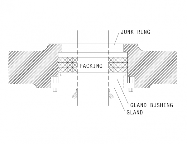 Many Pile Hammer mechanics have a tendency to tighten the Packing Gland too tight. A little steam or air leaking through the Packing is not objectionable. The oil mixed with the escaping air or steam will lubricate the Packing and Piston Rod.
TIP # 011 : STORAGE
Sometimes contractors forget that a Pile Driving Hammer is a machine and should be treated as such. Especially when the Hammer is to be stored for any length of time. Rust can create havoc in a Hammer. Sometimes the contractor takes a Hammer off of...
Read More
Tip #011: TIGHTENING THE PACKING GLAND
Sometimes contractors forget that a Pile Driving Hammer is a machine and should be treated as such. Especially when the Hammer is to be stored for any length of time. Rust can create havoc in a Hammer. Sometimes the contractor takes a Hammer off of a job and lays it down in the yard expecting that it will go out on another job the next day. But two years later the Hammer is still in the same spot and rusty. Following the steps below will take about 30 minutes and save the contractor many hours of down time and expense.
- To protect the columns and piston rod rod from rust during storage,wrap them with cloth, tie with wire and soak with oil. Grease on the columns and piston rod can be washed off with a heavy rain.
- Wrap the slide bar as above.
- Stuff oil soaked rags into the exhaust port in the valve chest.
- Pour a quart of oil in the air intake and seal with water proof tape.
- On the Single Acting Hammer pour a quart of oil into the exhaust port at the top of the cylinder and seal with waterproof tape.
- On the Differential Acting Hammer stuff oil soaked rags into the lower cylinder around the piston rod.
TIP # 012 : TROUBLE SHOOTING
A. Hammer Runs Too Slow: Possible Causes: Steam Or air pressure too low. Steam supply line too long or not proper size. Steam supply line restricted in some manner. Lack of lubrication. Worn or broken piston rings or scored cyl...
Read More
Tip #012: Trouble Shooting
A. Hammer Runs Too Slow:
Possible Causes:
- Steam Or air pressure too low.
- Steam supply line too long or not proper size.
- Steam supply line restricted in some manner.
- Lack of lubrication.
- Worn or broken piston rings or scored cylinder wall. Check this by allowing enough steam to enter the cylinder to hold the ram in about a half-raised position and note whether excessive steam is blowing out of exhaust ports at top of cylinder.
- Piston rod packing gland too tight.
- Excessive steam or air leakage. Blown gaskets or packing.
- Badly worn slide bar wedges or dovetail, or bent trip.
B. Hammer Runs Too Fast
Possible Causes:
- Excessive steam or air pressure on hard driving indicated by bouncing of hammer on up stroke.
- Ram not making full stroke.
C. Excessive Slide Bar Breakage
Possible Causes:
- Slide bar key loose.
- Worn dovetail.
D. Hammer Changes Speeds While Operating:
Possible Causes:
- Boiler or compressor not large enough.
- Boiler feed water allowed to drop too low.
- Loose or torn hose lining.
- Intermittent lubrication caused by defective or empty line lubricator.
- Loose slide bar or badly won dovetail.
E. Hammer Leaks Steam at Main Exhaust Port Constantly:
Possible Causes:
- Valve not seating properly.
- Scored or broken steam chest liner.
F. Hammer leaks Steam or Air Excessively From Exhaust at Top of Cylinder:
Possible Causes:
- Worn or broken piston rings.
- Scored cylinder wall.
G. Ram Hangs and Hammer Stops Operating:
Possible Causes:
- Loose tie cables.
- Rust or burrs on column.
- Piston rings too large and seized up in cylinder.
- Piston packing too tight.
- Bent columns.
Note: Both the Onshore and Offshore Field Service Manuals have troubleshooting guides. These can be found in the Vulcan Hammer Guide to Pile Driving Equipment.
TIP # 013 : ADAPTION OF MCDERMID BASE
We do not recommend the use of McDermid base for any type of pile other than wood. But on occasion, contractors have found themselves in a position whom they have had to adapt a McDermid base to standard Driving Heads or Pipe Caps. The above shows...
Read More
Tip #013: ADAPTION OF MCDERMID BASE
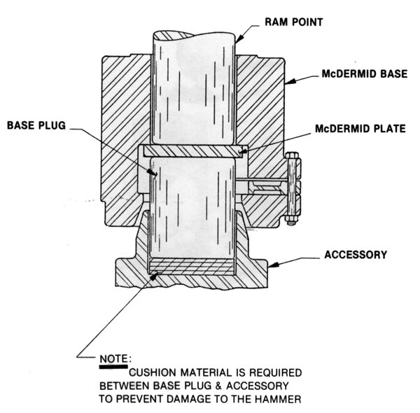 We do not recommend the use of McDermid base for any type of pile other than wood. But on occasion, contractors have found themselves in a position whom they have had to adapt a McDermid base to standard Driving Heads or Pipe Caps. The above shows the arrangement necessary to accomplish this.
Note: the McDermid Base was one of the first “customisations” applied to a Vulcan hammer. Vulcan licensed this from its inventor, Hugh McDermid. Although the conical cone on Vulcan bases was originally designed to mate with tapered wood pile heads, the McDermid Base gave better alignment. This is one of the few instances where a Vulcan hammer could drive the pile “directly,” i.e., without cushion material. Unfortunately hammers equipped with a McDermid Base could only drive wood piles, thus without adaptations such as this such a hammer was limited in its scope.
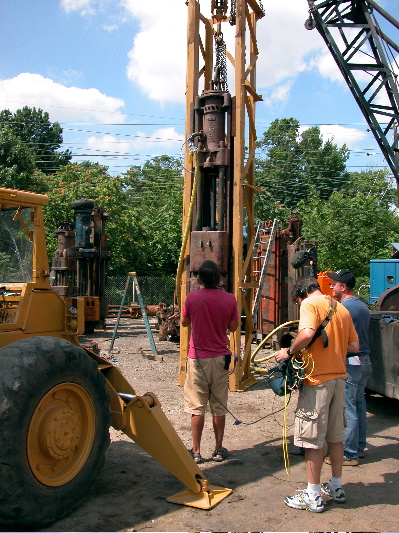 Vulcan #2 equipped with a McDermid Base being set up for a demonstration driving to be included in an episode of the History Channel.
TIP # 014 : VULCAN EXTRACTORS
The Vulcan Pile Extractor was the last major design by James N. Warrington (U.S. Patent 1,736,104) to enter production, which it did in 1928. The extractor uses a simple, valveless design where the ram is thrown upward by the incoming steam or air...
Read More
Tip #014: VULCAN EXTRACTORS
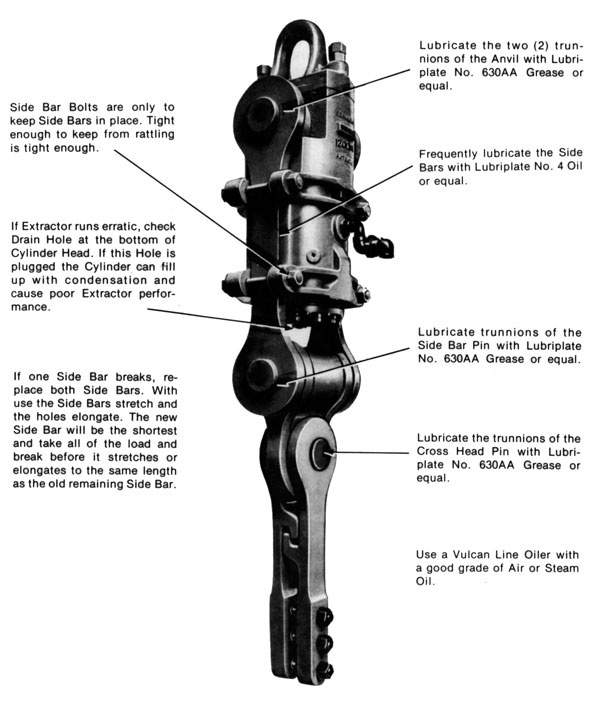 The Vulcan Pile Extractor was the last major design by James N. Warrington (U.S. Patent 1,736,104) to enter production, which it did in 1928.
The extractor uses a simple, valveless design where the ram is thrown upward by the incoming steam or air. It strikes an anvil located in the top of the machine. The impact force is transmitted through the side bars to the cross pin and onward to the connecting links.
Although it could in principle be used to extract any pile, Vulcan pile extractors were primarily used with sheet piling, as this type of piling is very common in temporary works. An example of this is shown at the right. The main method of connecting the extractor with the piles was through the two bolts that passed through the connecting links and the corresponding holes in the sheet piling, which the sheet pile supplier would commonly drill or burn in the sheeting.
In some cases the holes could be avoided by the use of Heppenstal tongs, which are similar in principle to the grips seen on impact-vibration hammers. Vulcan also developed and patented its own pile grips as well.
Vulcan’s main competitor was the MKT “E” series, which were very similar in construction. In the 1960’s Vulcan also marketed the Nilens series of extractors, which featured a cable wrap system for transmitting the impact along with a Heppenstal type grip.
Impact extractors represented the best way of removing sheet piles until the 1970’s, when the vibratory drivers took over the job. However, for smaller jobs where there were few sheets, or jobs where the sheets were embedded in very hard soil or the interlocks rusted or beaten together, the impact extractor remains a useful tool for removing sheet piles after their job is done.
TIP # 015 : BASE COLUMN KEYS
Loose Column Keys can shorten the life of a Hammer considerably. When the Base Keys are loose the Hammer is subject to misalignment and breakage. Loose Keys will slip into the center of the Base and be struck by the Ram Point, breaking the Base. The...
Read More
Tip #015: VULCAN EXTRACTORS
 The Vulcan Pile Extractor was the last major design by James N. Warrington (U.S. Patent 1,736,104) to enter production, which it did in 1928.
The extractor uses a simple, valveless design where the ram is thrown upward by the incoming steam or air. It strikes an anvil located in the top of the machine. The impact force is transmitted through the side bars to the cross pin and onward to the connecting links.
Although it could in principle be used to extract any pile, Vulcan pile extractors were primarily used with sheet piling, as this type of piling is very common in temporary works. An example of this is shown at the right. The main method of connecting the extractor with the piles was through the two bolts that passed through the connecting links and the corresponding holes in the sheet piling, which the sheet pile supplier would commonly drill or burn in the sheeting.
In some cases the holes could be avoided by the use of Heppenstal tongs, which are similar in principle to the grips seen on impact-vibration hammers. Vulcan also developed and patented its own pile grips as well.
Vulcan’s main competitor was the MKT “E” series, which were very similar in construction. In the 1960’s Vulcan also marketed the Nilens series of extractors, which featured a cable wrap system for transmitting the impact along with a Heppenstal type grip.
Impact extractors represented the best way of removing sheet piles until the 1970’s, when the vibratory drivers took over the job. However, for smaller jobs where there were few sheets, or jobs where the sheets were embedded in very hard soil or the interlocks rusted or beaten together, the impact extractor remains a useful tool for removing sheet piles after their job is done.
TIP # 016 : PIPING DO’S AND DON’TS
The length of the Nipple from the Inlet must be kept to a minimum. A long Nipple, as shown in the drawing, even though supported by chain or wire rope, will cause damaging leverage and vibration. Extensions to the side, like the arrangement in the ...
Read More
Tip #016: BASE COLUMN KEYS
 Loose Column Keys can shorten the life of a Hammer considerably. When the Base Keys are loose the Hammer is subject to misalignment and breakage. Loose Keys will slip into the center of the Base and be struck by the Ram Point, breaking the Base.
The drawing shows a quick and easy way to keep these keys tight and to retighten as the job progresses.
Weld the Ring to the Keys as shown. Then when the Key needs to be tightened, drive a “U” shaped washer between the Ring and Base. Drive as many washers as necessary to keep the Key tight. Then tack weld the washers to the Ring or Key, not the Base.
TIP # 017 : EXHAUST MUFFLERS
One thing most people notice first about pile driving jobs is that they generate an elevated level of noise. Until the 1960's, most people simply put up with this and many other aspects of industrialization and development. In the early 1970's, Vulca...
Read More
Tip #017: EXHAUST MUFFLERS
 One thing most people notice first about pile driving jobs is that they generate an elevated level of noise. Until the 1960’s, most people simply put up with this and many other aspects of industrialization and development. In the early 1970’s, Vulcan and other pile driving equipment manufacturers were confronted with new regulations–both at the federal and local level–which sought to regulate the noise output of construction equipment. Needless to say, pile driving equipment was high on the list.
Vulcan’s first reaction was to study the issue. It retained the services of United Acoustical Consultants in Glastonbury, CT, and its principal, Stannard Potter, to study the nature of noise output of Vulcan hammers. In December 1972 they conducted a study of a Vulcan #1 at the Chattanooga facility.
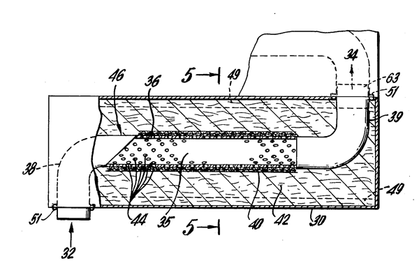
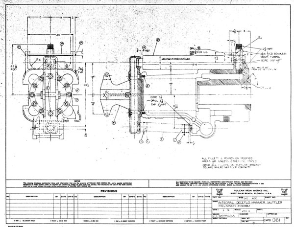
Vulcan hammers, although durable and simple, suffered from two specific difficulties for noise abatement: a) their open construction gave little natural noise attenuation, and b) their lack of a recoil dampener increased the impact load on the frame, thus making it difficult to attach shrouds and other devices to attenuate sound. However, one of the results of the study was that a large proportion of the sound emission from an operating Vulcan hammer came from the exhaust. Since muffling the exhaust was simpler than doing same with the impact, Vulcan commissioned Potter to design an exhaust muffler, which it called the Decelfo Muffler.
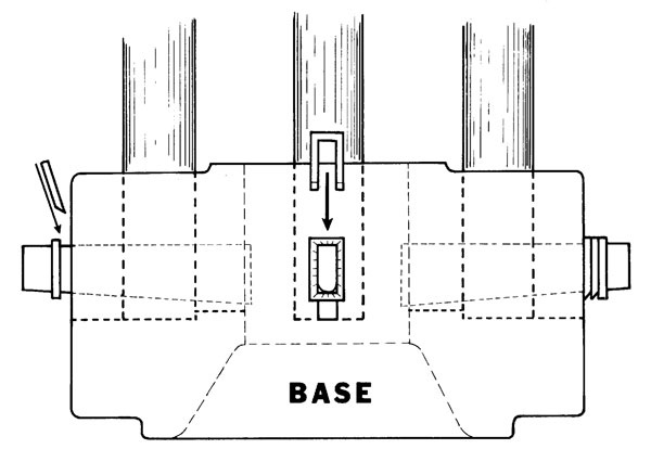
 The muffer was simple, a box which directed the air or steam output of the exhaust through perforated pipe surrounded by acoustical foam. The drawing shows a stacked arrangement for the muffler, but Vulcan never employed this arrangement.
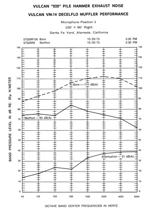
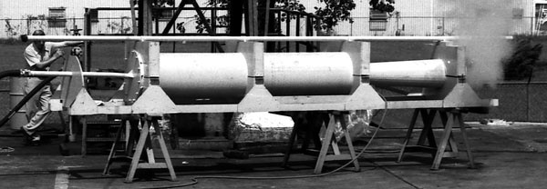
The first test of the Decelflo took place in October 1973 in the Alameda yard of Santa Fe construction in Alameda, California. It involved muffling a Vulcan 020 hammer.
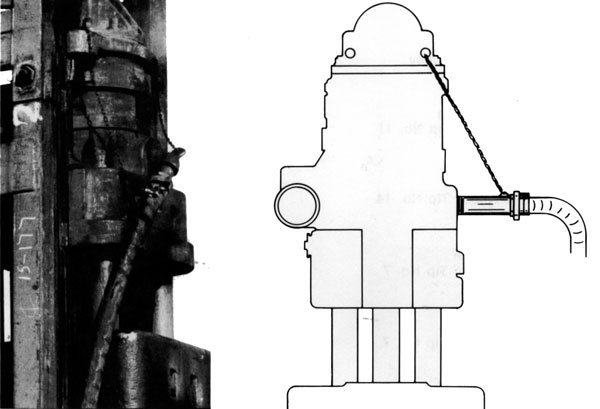
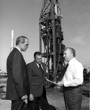
Right: setting up for the test. The muffler (the silver device at the top of the photo) is mounted on the hammer through the sheave pin, which principally is the centre shaft for the sheave wheels used to raise and lower the hammers. The bearings for the sheave pin on the muffler were connected to the muffer through rubber shock absorbers. The hammer’s exhaust was connected to the muffler using hose.
In front of the hammer Stan Potter (right) reviews the test procedure. At the left is Henry G. Warrington, Chairman of the Board and President.
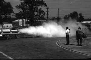
As shown below, the test was successful; the muffler performed as anticipated and its used resulted in reduction of hammer noise.
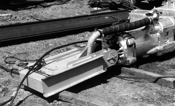
 Flush with this success, Vulcan continued in its development of the muffler. In July 1974 it had another opportunity to demonstrate (and verify) the Decelflo’s capabilities, this time in Chicago at a sheet piling project. Below: the Decelflo mounted on top of the Vulcan hammer, in this case a 50C. The hose connection from the exhaust port to the muffler can be clearly seen, along with its connection to the hammer via the sheave pin.
Vulcan had great plans for the Decelflo; at this time it was working on a method to mount the muffler directly on the hammer, as shown below. But then things took a strange twist.
 To begin with, there was considerable contractor resistance to the concept of having to add another device to the hammer assembly. Mounting it above the hammer lengthened the leaders required to operate the hammer, and the large installed base of Vulcan hammers dictated that this would be the normal way the muffler would be mounted.
Beyond that, the level of noise emissions, and how people perceive them, vary widely from one jobsite to another. This variation is a function of the location of the job (urban, remote, etc.), the presence or absence of neighbouring buildings to reflect the sound, and whatever ambient noise is in proximity to the jobsite. For example, driving piling next to an existing interstate, with the road noise already present, may not be very perceptible.
 Finally, as far as those working on the jobsite are concerned, contractors (and OSHA) found it simpler to deal with noise emissions from pile drivers and other equipment on site by providing hearing protection to the workers, which of course is standard on jobsites today.
In any case, the Decelflo muffler was never very popular, “noise pollution” never achieved the notoriety of air and water pollution, and both Vulcan and its customer base moved on to other concerns. For his part Stan Potter moved on to patent the Decelflo concept independently of Vulcan.
Thruflo (Geothermal) Muffer
The need to attenuate noise combined with another concern of the era, the need for alternative energy resources, with the geothermal muffer. An experimental product, it nevertheless touched on issues that are still important today.
Geothermal energy is possible when the hot magma which exists in the earth is close enough to the surface and the underground water to turn the latter into steam, which can be used to drive the turbines and generators to produce electric power. The means that the source of geothermal energy is not only free economically, but also that carbon dioxide (greenhouse gas) is not emitted in the production of electricity.
In the course of producing energy, the steam is vented to the atmosphere, and unmuffled this can produce a high noise level.
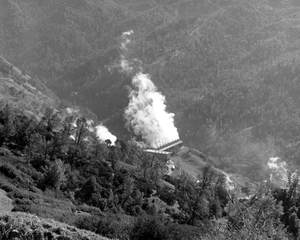
Below: the target for the geothermal muffer: The Geysers, a power generation plant north of San Francisco, CA, in February 1974.
Vulcan built a prototype and tested it in its own facility in August 1974.
Below: the Thruflo Geothermal Muffer, ready for acoustical testing. Above it is the straight pipe, against which it will be compared. Steam flowed from left to right.
Below: measuring the sound as the steam passes through the straight pipe (left) and the muffler (right.)
Unfortunately the Thruflo Muffer did not get past the prototype shown above. Some of the mufflers that did make it to The Geysers had a difficult time of it.
TIP # 018 : RAM KEY ADJUSTMENT
After a Hammer has a lot of "mileage" the parts that hold the Piston Rod to the Ram wear a little. This will necessitate some adjustment to insure proper tension of the Ram Keys. If this condition exists in your Hammer and the Ram Keys have a tendenc...
Read More
Tip #018: RAM KEY ADJUSTMENT
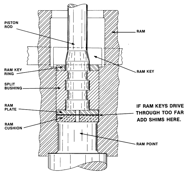 After a Hammer has a lot of “mileage” the parts that hold the Piston Rod to the Ram wear a little. This will necessitate some adjustment to insure proper tension of the Ram Keys. If this condition exists in your Hammer and the Ram Keys have a tendency to drive through too far, add Shims between the Ram Cushion and the Ram Plate.
TIP # 019 : VALVE LINER
All Hammers shipped from the factory now are equipped with a Valve Liner. When the Valve Seat area is worn the Valve Liner can easily and quickly be replaced. This eliminates the old time consuming and expensive re-machining of the Valve Seat. The...
Read More
Tip #019: VALVE LINER
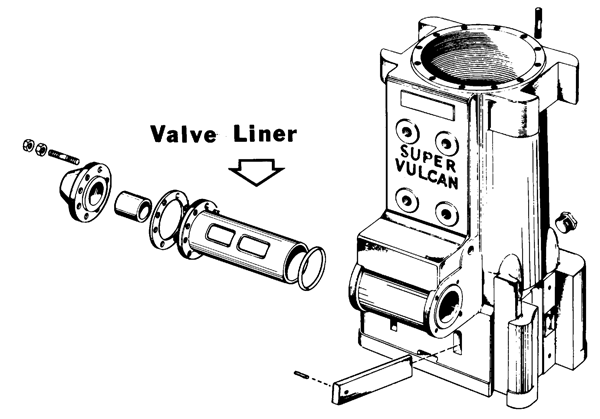 All Hammers shipped from the factory now are equipped with a Valve Liner. When the Valve Seat area is worn the Valve Liner can easily and quickly be replaced. This eliminates the old time consuming and expensive re-machining of the Valve Seat. The Liner also allows Valve timing in the field with field tools and less than an hour’s time.
Old style Vulcan Hammers can be machined to fit the new Liner. Contact the factory for instructions.
TIP # 020 : EXTRACTOR BUMPER CONVERSION
Until recent years Vulcan Pile Extractors utilized a Steel Spring and Spring Guide in the Cylinder head as shown below: To convert older Extractors to the new configuration which replaces the Spring and Spring Guide with a Rubber Bumper the pr...
Read More
Tip #020: EXTRACTOR BUMPER CONVERSION
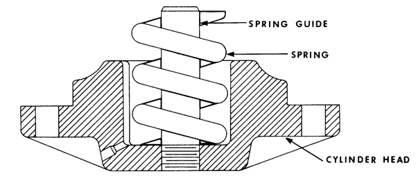
Until recent years Vulcan Pile Extractors utilized a Steel Spring and Spring Guide in the Cylinder head as shown below:
To convert older Extractors to the new configuration which replaces the Spring and Spring Guide with a Rubber Bumper the procedure is as follows:
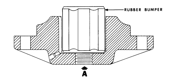
- Drill through at “A” 1 1/2″ diameter.
- Remove Spring Guide and discard.
- Tap hole for 1 1/4″ NPT.
- Insert countersunk Pipe Plug 1 1/4″ size.
- Install Bumper as shown.
TIP # 021 : SLIDE BAR SHIM
When checking the position of the Slide Bar if you find it below the correct position, add the Shim BELOW THE SLIDE BAR END BLOCK, as shown above. Shims installed under the Slide Bar, for obvious reasons, will create problems...
Read More
Tip #021: SLIDE BAR SHIM
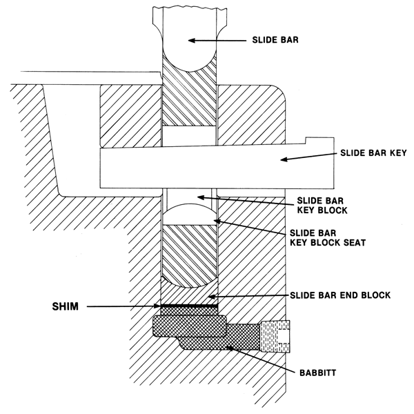 When checking the position of the Slide Bar if you find it below the correct position, add the Shim BELOW THE SLIDE BAR END BLOCK, as shown above. Shims installed under the Slide Bar, for obvious reasons, will create problems.
TIP # 022 : REPLACING SLIDE BAR BABBITT
Remove Ram Pipe Plug. Remove old Babbitt by melting with torch. Position Slide Bar "A" and Slide Bar End Block "B" with respect to Ram boss area. Pour molten Babbitt into cavity at "C" until the Babbitt is 3/4" from the outer surface of the...
Read More
Tip #022: REPLACING SLIDE BAR BABBITT
- Remove Ram Pipe Plug.
- Remove old Babbitt by melting with torch.
- Position Slide Bar “A” and Slide Bar End Block “B” with respect to Ram boss area.
- Pour molten Babbitt into cavity at “C” until the Babbitt is 3/4″ from the outer surface
of the Ram.
- Reinstall Ram Pipe Plug after Babbitt has solidified.
Caution: Use only medium hard Babbitt metal equivalent to Glyco B. DO NOT USE LEAD.
Note: Many compositions of Babbitt contain lead. Be sure to follow all applicable safety and environmental regulations when using babbitt. At one point, Tennessee OSHA required Vulcan to conduct airborne lead tests in the assembly area where babbitt was used. Lead levels detected were below applicable standards. Your results may vary.
TIP # 023 : INSERTING NEW RAM POINT IN RAM
Vulcan Hammer Guide To Pile Driving Equipment...
Read More
TIP # 024 : REMOVING BROKEN RAM POINT
When Ram Point failures occur. it is generally true that they break through he neck of the point at or near the bottom surface of the Ram. It is most usually almost impossible to press out the broken neck portion of the point from the Ram. The proper...
Read More
Tip #024: REMOVING BROKEN RAM POINT
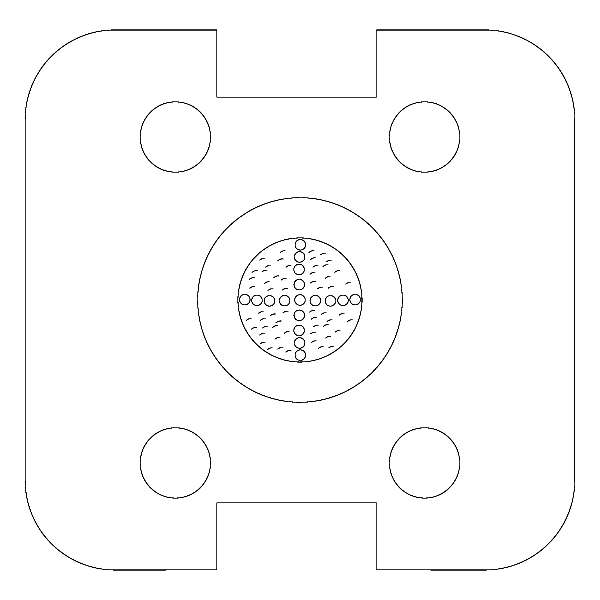 When Ram Point failures occur. it is generally true that they break through he neck of the point at or near the bottom surface of the Ram. It is most usually almost impossible to press out the broken neck portion of the point from the Ram. The proper and easiest method of removal is as follows:
- If the Ram Point is pinned, it is necessary to drill out the Pins prior to proceeding.
- After Pins (if present) are removed, drill a series of holes (see below) in a cross configuration through the Ram Point neck portion. Do not place these holes closer than 1/4″ to the Base into which the Ram Point is fitted. With a torch, burn the metal from between the series of holes drilled. This will relieve the radial pressure on the Ram Point. After this is done, press out the remaining portion of the Ram Point.
Depending on bore condition it may be necessary to hone or re-bore the Ram. This should be done before inserting new Ram Point.
TIP # 025 : SIDE CHANNEL MODIFICATION
Many of our contractor customers have in the past modified the installation of Pile Hammer Side Channels to provide the following: Spring mounting of Channels to prevent attrition during extremely hard driving. Spring mounting of a Hammer Ada...
Read More
Tip #025: SIDE CHANNEL MODIFICATION
Many of our contractor customers have in the past modified the installation of Pile Hammer Side Channels to provide the following:
- Spring mounting of Channels to prevent attrition during extremely hard driving.
- Spring mounting of a Hammer Adapter to adapt one size Hammer to a larger size set of Leaders.
In either case we can provide special Cylinder Head attachments and hardware to implement both alternatives as illustrated below:
Note: What is presented here is a variation of another Raymond innovation: the inboard extension. All Raymond hammers were designed to ride in some kind of extension. The advantage of this is that it makes mating a system of hammers and leaders much simpler if the hammers can be run in more than one set of jaws, and an extension system is the easiest way to accomplish this.
One innovation that Raymond eventually went to was the use of rubber springs in place of the coil ones. In addition to lesser expense, when properly selected the rubber springs do a better job of dampening the hammer vibrations than the steel coil ones. It’s important that the structural integrity of the extension is sufficient to withstand both vibration and handing stresses.
Below: Vulcan 06 hammer riding in an extension.
TIP # 026 : COLUMN REMOVAL
It is frequently encountered when overhauling Pile Hammers that Columns will be stuck in the Cylinder and occasionally in the Base of the Hammer. This occurs for many reasons ranging from excessive corrosion or badly burred parts. The easiest way to...
Read More
Tip #026: COLUMN REMOVAL
It is frequently encountered when overhauling Pile Hammers that Columns will be stuck in the Cylinder and occasionally in the Base of the Hammer. This occurs for many reasons ranging from excessive corrosion or badly burred parts. The easiest way to remove such Columns is shown below.
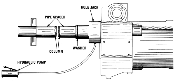
- Use a center hole jack (100 ton capacity) with sufficient hole diameter to slide over the Column. This should be so positioned so that the ram of the jack is away from the Cylinder, (i.e.) thrust in direction of arrow.
- Use a 3/4″ thick washer of suitable inside diameter.
- For the length of the Column from the jack to the keyway insert a pipe spacer.
- Insert in the keyway of the Column a Column Key or steel bar to provide backup for jacking.*
- After this assembly is complete, commence jacking.
*If the lower end of the Column is broken off and no full keyway is available lugs may be welded to the Column to provide jacking back-up.
Note: The tip is not clear on this, but the procedure described above probably only applies to smaller Vulcan hammers.
Jacking columns and other parts out of rusted or well used hammers is a procedure that occurs regularly in the overhaul of Vulcan hammers. It is one, however, that requires special attention to safety. The parts used must be thick enough to withstand the loads, and personnel must stand clear during the operation in case a part gives way and results in a “missile reaction.”
TIP # 027 : BUSHING REPLACEMENT
The use of bronze bushings in Vulcan products is limited to head sheaves and steam chest heads. From time to time it is necessary to replace these bushing. All of these bushings are press fitted. Sometimes the parts into which these bushings are pres...
Read More
Tip #027: BUSHING REPLACEMENT
The use of bronze bushings in Vulcan products is limited to head sheaves and steam chest heads. From time to time it is necessary to replace these bushing. All of these bushings are press fitted. Sometimes the parts into which these bushings are pressed are oversize in bore for a variety of reasons. When this occurs. the factory supplied bushing will not fit tightly. Rather than make a special bushing, there is a simple method of adjusting the fit of the bushings for press fitting.
| Step I — Place bushing on an arbor and put in engine lathe. Using fine diamond-point knurling rolls, double knurl the outer surface of the bushing. Be sure to use a good quality cutting oil during the knurling operation. After knurling, degrease the bushing prior to proceeding with the next step. |

|
| Step 2 — Make sure that the hole into which the bushing is to be inserted is clean, dry and free of burrs. The outside of the bushing should look like the illustration. Using no lubricant press the bushing into the piecepart. |

|
TIP # 028 : INSTALLATION OF BLIND PISTON RINGS
Lower piston rings in the case of the Super Vulcan and the DGH series hammers, and upper piston rings in the case of Vulcan Pile Extractors, require a special installation technique. This special technique is necessitated by the fact that in these th...
Read More
Tip #028: INSTALLATION OF BLIND PISTON RINGS
Lower piston rings in the case of the Super Vulcan and the DGH series hammers, and upper piston rings in the case of Vulcan Pile Extractors, require a special installation technique. This special technique is necessitated by the fact that in these three product lines, the piston and the piston rings affixed thereto must enter the cylinder in which they function unaided by such devices as piston ring compressors or installers. Additionally it is impossible to visually check the piston ring as it enters its cylinder. The procedure is not unduly complicated if the following steps are carefully executed. The three illustrations below show the general method to be described in steps.
- Examine carefully the piston ring grooves for any burrs or dirt. Deburr if necessary and make sure the grooves are clean.
- Expand the piston rings and snap them into their respective grooves making sure that they rotate freely.
- Raise the end of the piston ring at the gap with a fine point screwdriver or other sharp instrument and place behind the ring a piece of water soluble paper (cigarette paper or toilet tissue is suitable for this purpose).
- Using a lead or bronze hammer, carefully tap the piston ring at the point of insertion of the paper into the groove where it will be wedged in place by the paper.
- Repeat this procedure with the other end of the piston ring and in the process or tapping the ring into the groove, be sure that the gap in thepiston ring is as nearly closed as possible.
- After the rings are so wedged into the grooves, the piston is now ready for installation in the unit.
Moisture in the steam or compressed air will soften the paper used to wedge the rings and they will expand to their normal operating position in a short period of time after the unit is laced in operation.
TIP # 029 : EQUIPMENT HANDLING
While Pile Hammers are not unduly difficult to handle there are some basic precautions to be observed as well as some basic Do's and Don'ts. Note: Hammer handing as "not unduly difficult" only applies to specialists in material handing...
Read More
Tip #029: EQUIPMENT HANDLING
While Pile Hammers are not unduly difficult to handle there are some basic precautions to be observed as well as some basic Do’s and Don’ts.
Note: Hammer handing as “not unduly difficult” only applies to specialists in material handing.
TIP # 030 : STRIPPED THREAD REPAIRS
It is frequently found in older hammers that stud hole threads will sometimes become stripped of sufficient holding thread as to necessitate some form of repair. Generally speaking there am two alternate methods of effecting this repair the first is...
Read More
Tip #030: STRIPPED THREAD REPAIRS
It is frequently found in older hammers that stud hole threads will sometimes become stripped of sufficient holding thread as to necessitate some form of repair. Generally speaking there am two alternate methods of effecting this repair the first is to drill out oversize the stripped hole, insert a plug and redrill and retap to original size. The second alternate is to drill out the stripped hole oversize and install oversize studs or screws as the case may be. The disadvantage to this is it is then necessary to resize the holes in the mating parts.
The recommended procedure is the use of Heli-Coil®. Heli-Coil inserts are thread bushings coiled from formed diamond shaped wire. They are wound into tapped holes to form Standard size internal threads. The procedure is simple.
Step I – Drill out the stripped hole with the specified drill size to the appropriate Heli-Coil insert.
Step 2 – Tap the new hole with special Heli-Coil tap.
Step 3 – Install thread sleeve with Heli-Coil inserter and your tapped hole is back to standard.
The Heli-Coil salvage procedure is acceptable to military and industrial standards and affords easy repair to your hammers and extractors. Heli-Coil products while not sold by Vulcan Iron Works Inc- are available from Heli-Coil Products, Division of Mite Corporation, Danbury, Connecticut 06810, or their distributors. This type of product is normally marketed through industrial mill supply houses.
Heli-Coil® is the registered trade mark of the Mite Corporation.
TIP # 031 : BROKEN STUD REMOVAL
Probably one of the most annoying problems in hammer repair is the removal of broken studs or screws. Shown below is an easy and proven method of removing the broken portion of the stud or screw without damage to the tapped hole. Apply generous...
Read More
Tip #031: BROKEN STUD REMOVAL
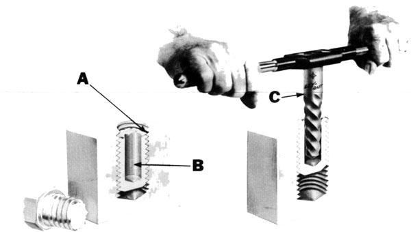 Probably one of the most annoying problems in hammer repair is the removal of broken studs or screws. Shown below is an easy and proven method of removing the broken portion of the stud or screw without damage to the tapped hole.
- Apply generous quantity of penetrating oil to stub of stud and let stand overnight if possible (Letter A).
- Drill hole in broken stud as shown (Letter B). See table below for size of drill.
- Using Ezy-Out® as shown (Letter C) back out broken portion of stud. See table below for size of Ezy-Out®.
|
EZY-OUT® NO.
|
DRILL SIZE
|
STUD/SCREW SIZE
|
|
5
|
17/64″
|
9/16″-3/4″
|
|
6
|
13/32″
|
3/4″-1″
|
|
7
|
17/32″
|
1″-1 3/8″
|
|
8
|
13/16″
|
1 3/8″-1 3/4″
|
|
9
|
1 1/16″
|
1 1/34″-2 1/8″
|
|
10
|
1 5/16″
|
2 1/8″-2 1/2″
|
|
11
|
1 9/16″
|
2 1/2″-3″
|
|
12
|
1 15/16″
|
3″-3 1/2″
|
|
EZY-OUT® IS THE REGISTERED TRADEMARK OF THE CLEVELAND TWIST DRILL CO.
|
TIP # 032 : COLUMN SALVAGE
Vulcan Hammer Guide To Pile Driving Equipment...
Read More
TIP # 033 : BASE/CYLINDER COLUMN HOLE REPAIR
Tip no longer available, due to involved nature of repair...
Read More
Tip #033: BASE/CYLINDER COLUMN HOLE REPAIR
Tip no longer available, due to involved nature of repair.
TIP # 034 : STEAM CHEST VALVE LINERS
Replaceable Steam Chest Valve Liners are standard equipment in all Vulcan Single and Differential Acting Pile Hammers These Valve Liners were adopted to provide easy means of replacing worn surfaces in the Steam Chest in lieu of reboring. Given belo...
Read More
Tip #034: STEAM CHEST VALVE LINERS
Replaceable Steam Chest Valve Liners are standard equipment in all Vulcan Single and Differential Acting Pile Hammers These Valve Liners were adopted to provide easy means of replacing worn surfaces in the Steam Chest in lieu of reboring.
Given below in the table are the Serial Numbers and dates of the first hammer in each size to be equipped with Valve Liners. All hammers with Serial Numbers subsequent to those given for each size of Hammer are equipped with Valve Liners.
As changes take place. additional data will be provided.
| Hammer Size |
Serial Number & Date
|
| Onshore Std. |
Onshore Cable |
Offshore (Raised Steam Chest) |
Offshore (Lowered Steam Chest) |
| #2 |
FG-5335/11-29-67 |
|
|
|
| #1 |
FG-5280/10-23-67 |
|
|
|
| 06 |
FG-5465/12-21-67 |
|
|
|
| 106 |
FI-6180/4-21-69 |
|
|
|
| 08 |
FG-5205/9-11-67 |
GD-9200/12-4-74 |
|
|
| 010 |
FG-5240/9-27-67 |
GD9035/8-8-74 |
|
FJ-6700/6-26-70 |
| 014 |
FG-5345/12-16-67 |
|
|
|
| 016 |
FI-6335/7-15-69 |
|
|
FG-4075/4-4-67 |
| 020 |
FG-5190/8-19-67 |
|
|
FH-5530/2-24-68 |
| 030 |
|
|
|
FH-5645/4-19-68 |
| 040 |
|
FI-6240/5-8-69 |
|
FG-5330/12-8-67 |
| 340 |
|
|
|
GC-8245/2-12-73 |
| 540 |
|
|
|
GD-8800/5-22-74 |
| 060 |
|
|
|
FH-5555/6-15-68 |
| 360 |
|
|
|
GD-9025/7-19-74 |
| 560 |
|
|
|
GC-8445/7-18-73 |
| 3100 |
|
|
|
GE-9450/6-11-75 |
| 30C |
FH-5520/2-12-68 |
|
|
|
| 50C |
FG-5150/9-22-67 |
FH-5805/8-15-68 |
|
|
| 65C |
FG-5300/11-2-67 |
|
|
|
| 80C |
FG-4040/2-17-67 |
|
|
|
| 85C |
FI-6100/1-7-69 |
|
|
|
| 100C |
GA-7590/11-12-71 |
|
|
|
| 140C |
FF-3005/1-20-67 |
|
|
|
| 200C |
FH-5570/3-8-68 |
|
GA-7595/11-11-71 |
|
Note: This was never followed up on. But in reality there was no need to, as virtually any Vulcan hammer made after 1970 (those with a serial number starting with a “G”, “H” or “I”) had a valve liner. In addition to providing a replaceable wear surface, the valve liner eliminated the need to cut the valve stems custom for each hammer by providing a consistent location for the ports.
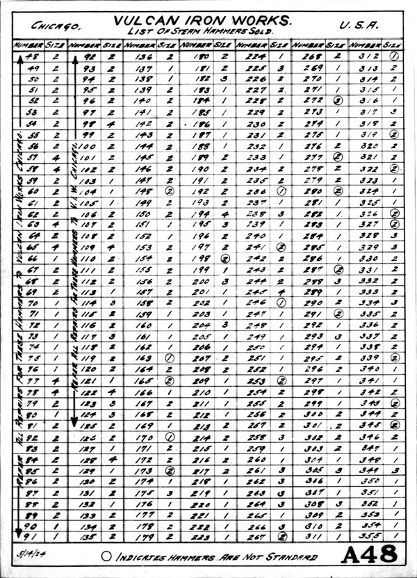
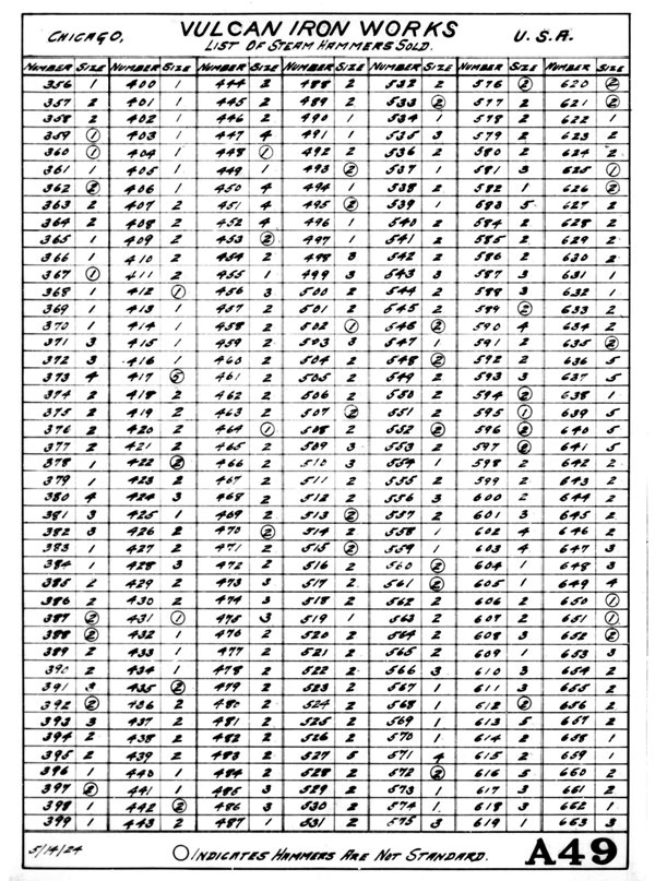
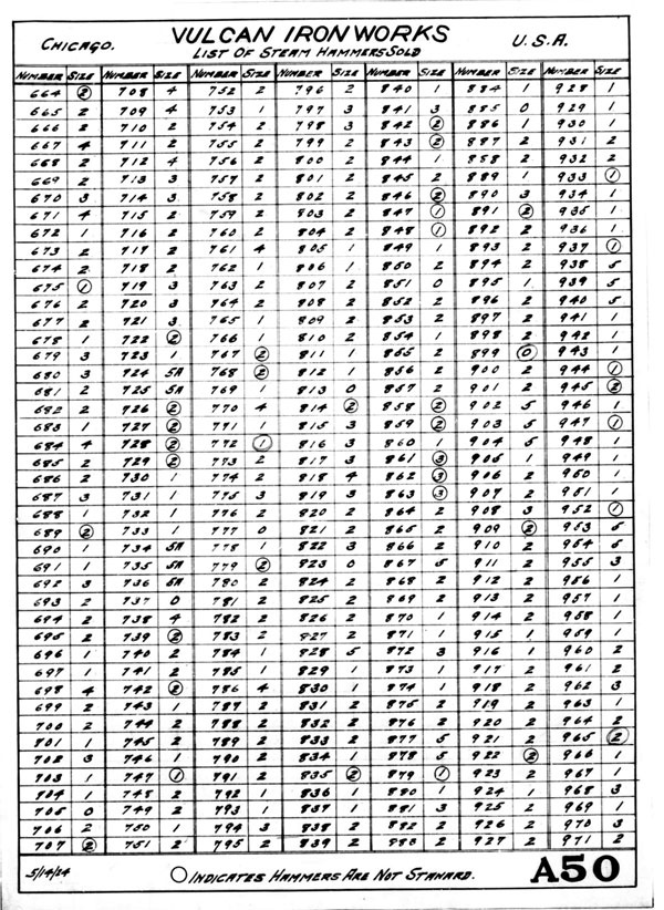
TIP # 035 : SERIAL NUMBERS
It is frequently desirable to ascertain the age of equipment for appraisal, evaluation and a variety of other reasons. As is customary in most construction equipment, we show below the year of manufacture and the serial number range for that particul...
Read More
Tip #035: SERIAL NUMBERS
It is frequently desirable to ascertain the age of equipment for appraisal, evaluation and a variety of other reasons. As is customary in most construction equipment, we show below the year of manufacture and the serial number range for that particular year. As we approach one hundred years of serial numbers, we will on a yearly basis update this information.
| YEAR |
S/N RANGE |
YEAR |
S/N RANGE |
YEAR |
S/N RANGE |
YEAR |
S/N RANGE |
| 1888 |
1/7 |
1913 |
771/832 |
1938 |
2504/2546 |
1963 |
48569/48667 |
| 1889 |
8/13 |
1914 |
833/912 |
1939 |
2547/2586 |
1964 |
48668/48777 |
| 1890 |
14/36 |
1915 |
913/994 |
1940 |
2587/2671 |
1965 |
48778/48855
FE665/FE1290 |
| 1891 |
37/45 |
1916 |
995/1041 |
1941 |
2672/2806 |
1966 |
FF1295/FF3050 |
| 1892 |
46/60 |
1917 |
1042/1115 |
1942 |
2807/2902 |
1967 |
FG3055/FG5475 |
| 1893 |
61/73 |
1918 |
1116/1197 |
1943 |
2903/2970 |
1968 |
FH5480/FH6000 |
| 1894 |
74/86 |
1919 |
1198/1231 |
1944 |
2971/3157 |
1969 |
FI6005/FI6555 |
| 1895 |
87/98 |
1920 |
1232/1259 |
1945 |
3158/3199 |
1970 |
FJ6700/FJ6755
GJ6760/GJ7175 |
| 1896 |
99/110 |
1921 |
1260/1321 |
1946 |
3200/3259 |
1971 |
GA7185/GA7670 |
| 1897 |
111/124 |
1922 |
1322/1374 |
1947 |
3260/3328 |
1972 |
GB7675/GB8200 |
| 1898 |
125 |
1923 |
1375/1431 |
1948 |
3329/3404 |
1973 |
GC8205/GC8690 |
| 1899 |
126/148 |
1924 |
1432/1517 |
1949 |
3405/3464 |
1974 |
GD8695/GD9270 |
| 1900 |
149/157 |
1925 |
1518/1591 |
1950 |
3465/3571 |
1975 |
GE9275/GE9720 |
| 1901 |
158/194 |
1926 |
1592/1665 |
1951 |
3572/3663 |
1976 |
GF100/GF470 |
| 1902 |
195/231 |
1927 |
1666/1777 |
1952 |
3664/3747 |
1977 |
See Note Below |
| 1903 |
232/241 |
1928 |
1778/1906 |
1953 |
3748/3826 |
1978 |
| 1904 |
242/287 |
1929 |
1907/2039 |
1954 |
3827/3898 |
1979 |
| 1905 |
288/352 |
1930 |
2040/2164 |
1955 |
3899/4012 |
1980 |
| 1906 |
353/411 |
1931 |
2165/2258 |
1956 |
4013/4214 |
1981 |
| 1907 |
412/461 |
1932 |
2259/2300 |
1957 |
4215/4363 |
1982 |
| 1908 |
462/507 |
1933 |
2301/2324 |
1958 |
4364/4488 |
1983 |
| 1909 |
508/548 |
1934 |
2325/2364 |
1959 |
4489/4623 |
1984 |
| 1910 |
549/604 |
1935 |
2365/2379 |
1960 |
4624/4747 |
1985 |
| 1911 |
605/690 |
1936 |
2380/2450 |
1961 |
4748/48335 |
1986 |
| 1912 |
691/770 |
1937 |
2451/2503 |
1962 |
48336/48568 |
1987 |
Note: This tip, issued in 1976, was never followed up on; there were never any updates for the offshore tips (there was one in 1977 for the onshore ones; the information from that one is included above.) In fact, by the 1980’s Vulcan took this tip out of its distribution list in fear of people knowing the number of Vulcan hammers outstanding.
However, such updates were, in reality, unnecessary, because in 1965 Vulcan adopted its present system of serial numbers for hammers. This system gave the year of the hammer’s manufacture without having to consult the factory. All of this type of serial number is in the format of
XX-YYYY
where “XX” represents the year code in two letters; they translate into the last two digits of the year as shown in the table on the left. Thus, for a hammer with the serial number prefix “GF” this translates into “76”, thus the hammer was made in 1976. The implementation of these numbers can be seen above.
If you would like more information on this subject, or on a specific hammer serial number, you can fill out the form below and submit it.
TIP # 036 : DOVETAIL REPAIR
As your Vulcan Offshore Hammers grow older, it is unavoidable that wear occurs in the Dovetail Guide in the Cylinder that guides and retains the slide bar. Excessive wear in this Dovetail Guide can cause damage to not only the Slide Bar but the Trip...
Read More
Tip #036: Dovetail Repair
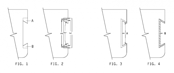 As your Vulcan Offshore Hammers grow older, it is unavoidable that wear occurs in the Dovetail Guide in the Cylinder that guides and retains the slide bar. Excessive wear in this Dovetail Guide can cause damage to not only the Slide Bar but the Trip and the Valve Stem. Where replaceable dovetail inserts are not standard equipment, the following methods of dovetail repair are recommended- Two repair methods are shown below in 1 & 2 depending on wear conditions in the Dovetail.
Repair method I is recommended when the majority of the wear has taken place on the angular surface of the Dovetail and the bottom flat surface does not require repair. The steps to follow for repair are as follows:
- Remove by machining worn dovetail surfaces as shown at A & B, Illustration #1.
- Manufacture BRONZE replacement gibs of appropriate size. as shown at C, Illustration #2. SAE 660 Bronze is recommended.
- Drill and tap Cylinder for cap screws as shown at D, Illustration #2.
- After installation of gibs, it is necessary to centerpunch each cap screw in at least three locations on its periphery to prevent backout as shown at E, Illustration #2.
Repair method 2 is recommended when wear has taken place on all three Dovetail surfaces (bottom and two angular sides). The steps to follow for repair are as follows:
- Remove by machining 1/16″ of surface metal on all three surfaces as shown at A, Illustration #3. This is to remove work hardened surfaces from worn areas.
- Build up all three surfaces with sufficient material to allow for remachining by either of the following methods:
- Arc brazing with Bronze rod.
- Arc welding with 100% Nickel rod.
- Gas brazing and gas welding are not recommended for cast iron material in this area of the cylinder.
- Remachine built up Dovetail area back to original factory dimensions as at B, Illustration #4.
IMPORTANT
When restoring Slide Bar Dovetails, it is absolutely essential that restored surfaces conform to original dimensional relationships with the center lines of the cylinder and Valve Chest. Contact factory for specific dimensions before proceeding.
Note: Method #1 seldom addresses real dovetail repair problems because the dovetail seldom wears only on the angled surfaces, but on the back as well. A more satisfactory solution to this problem would be to use the removable and replaceable Slide Bar Guide Block as Raymond used, but Vulcan never adopted this solution on its hammers.
TIP # 037 : VARI-CYCLE HAMMERS
Vulcan Vari-Cycle (Stroke Control) is available for all Vulcan Single Acting Hammers having a cylinder which has as an integrally cast pad part thereof the necessary mounting pads for installation of the Vari-Cycle equipment. Shown in the table below...
Read More
Tip #037: VARI-CYCLE HAMMERS
Vulcan Vari-Cycle (Stroke Control) is available for all Vulcan Single Acting Hammers having a cylinder which has as an integrally cast pad part thereof the necessary mounting pads for installation of the Vari-Cycle equipment. Shown in the table below are the first Serial Number and date of those hammers (by size) having Vari-Cycle factory installed or mounting pads for field retrofit.
| Hammer Size |
Serial Numbers and Date |
| Onshore Hammers |
Offshore Hammers |
| #1 |
See Note 1 |
– |
| 06 |
See Note 2 |
– |
| 08 |
GB-8095/10-27-72 |
– |
| 010 |
GB-8100/11-2-72 |
– |
| 014 |
FI-6250/5-13-69 |
– |
| 016 |
FI-6515/12-19-69 |
FH-5500/2-1-68 |
| 020 |
FG-5190/12-19-69 |
FH-5530/2-15-68 |
| 030 |
– |
FH-5645/4-19-68 |
| 040 |
– |
FG-5330/12-8-67 |
| 340 |
– |
GC-8245/2-12-73 |
| 540 |
– |
GD-8800/5-22-74 |
| 060 |
– |
FH-5555/6-15-68 |
| 360 |
– |
GD-9025/7-19-74 |
| 560 |
– |
GC-8445/7-18-73 |
| 3100 |
– |
GE-9450/6-11-75 |
All Hammers having Serial Numbers subsequent to those above are configured as to accommodate Vari-Cycle.
Note 1 — The following Size #1 Hammers are equipped with mounting pads for Vari-Cycle:
GC-8455/GC-8555/GC-8595/GC-8715/GC-8765
Vari-Cycle mounting pads on this size Hammer were discontinued 8-23-74.
Note 2 — The following Size 06 Hammers are equipped with mounting pads for Vari-Cycle:
GD-8750/GD-8740/GD-8825/GD-8605/GC-8605/GC-8685
Van-Cycle mounting pads on this size Hammer were discontinued 7-24-74
Note: This tip obviously does not cover the hammers later than the mid-1970’s, especially the onshore 5′ stroke hammers. Their situation is complicated; you can contact us to ask questions about this. All of the Vulcan 5100, 5110, 5150 and 6300 hammers can accommodate Vari-Cycle and indeed virtually all offshore hammers from the 1970’s onward were either equipped with Vari-Cycle or Traverse Trip.
TIP # 038 : COMPRESSED AIR VELOCITY FUSE
In the new Department of Labor hammer-tips Regulations for Construction, it states in the Federal Register, Volume 36, Number 75, that "all hoses exceeding 1/2 inch inside diameter shall have a hammer-tips device at the source of supply or branch line to reduc...
Read More
Tip #038: COMPRESSED AIR VELOCITY FUSE
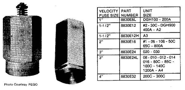 In the new Department of Labor Safety Regulations for Construction, it states in the Federal Register, Volume 36, Number 75, that “all hoses exceeding 1/2 inch inside diameter shall have a safety device at the source of supply or branch line to reduce pressure in case of hose failure.”
The “Velocity Fuses” shown below left now enable you to meet these requirements. They are specifically designed for use on compressed air lines loading to pneumatic tools These valves protect personnel from dangerous whipping air hoses caused by a suddenly disconnected coupling or severed air hose while the line is under pressure.
OPERATION
The valve automatically slams shut when the flow of air exceeds the setting of the valve. A tiny orifice or “bleed hole” allows enough air through the valve to equalize pressure. After repairs are made and air pressure is back to normal flow, the valve automatically re-opens to allow full flow and afford the same protection again The velocity fuses referred to above in sizes 1″ and larger are also suitable for steam operation.
The velocity fuse is a product of the REGO Division of Golconda Corporation, 4201 West Peterson Avenue, Chicago, Illinois 60646. They are available from REGO and/or their distributors throughout the country.
Note: this tip has taken something of a “life of its own” since it is one of the few references to compressed air velocity fuses on the net. We do not have further information on this item.
TIP # 039 : WINTER OPERATION
Cold weather operation of Pile Hammers and Pile Extractors on compressed air frequently presents problems of ice accumulation in valve assemblies and air passage ports. Icing is a function of temperature and humidity and causes erratic equipment oper...
Read More
Tip #039: WINTER OPERATION
Cold weather operation of Pile Hammers and Pile Extractors on compressed air frequently presents problems of ice accumulation in valve assemblies and air passage ports. Icing is a function of temperature and humidity and causes erratic equipment operation. There are several remedies for this problem which will help eliminate the icing condition:
- Install on your compressor the Vulcanaire Supertherm. At 400° F air temperature, ice is nonexistent.
- In your air line oiler, dilute your lubricating oil with an equal amount of ethylene glycol.
- Install in the air line between the Lubricator and the Hammer a Tanner De-lcer Tank. The Tanner De-lcer atomizes the anti-icing chemical into the airstream to prevent Hammer icing. Tanner gas equipment is available from Tanner Systems, Inc., Sauk Rapids, Minnesota 56379.
Always remember that in subfreezing weather it is essential to preheat the Hammer Cylinder prior to commencing daily operation. This is necessary to eliminate any frozen condensate inside tile Cylinder and Valve. It is also necessary to prevent possible cracking of the Cylinder due to thermal shock.
During winter operation, it is advisable to be sure that all condensate is expelled from the Lubricator at the end of the shift so that it will not be allowed to freeze thereby plugging the oil suction line. It is also advisable to preheat the Lubricator to assure immediate lubrication when operations are commenced.
If your crane boom is hard piped part way up, it is desirable that this piping be insulated to help minimize losses in air volume due to cooling.
Note: use of these procedures may be affected by environmental regulations.
TIP # 040 : OUTBOARD BRACKET SHIMS
On all Vulcan and Super Vulcan Offshore Pile Hammers, and all Vulcan Hammers equipped for Vari-Cycle, there is an extension of the Open Steam Chest Head (see illustration) called the "Outboard Bracket." This serves not only as a guard to protect the...
Read More
Tip #040: OUTBOARD BRACKET SHIMS
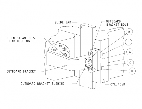 On all Vulcan and Super Vulcan Offshore Pile Hammers, and all Vulcan Hammers equipped for Vari-Cycle, there is an extension of the Open Steam Chest Head (see illustration) called the “Outboard Bracket.” This serves not only as a guard to protect the Slide Bar from damage and cables, but It also serves as an outboard bearing for the extended end of the Valve Stem.
It is absolutely essential In the final installation that the outboard bearing be right in line with the bore of the Bushing in the Open Steam Chest Head. Due to unavoidable differences in the manufacture of the Cylinder and the Outboard Bracket, a certain amount of Selective Assembly is necessary.
Inasmuch as the foot of the Outboard Bracket is bolted to the Cylinder. it is easy to create misalignment by excessive bolting pressure. It is therefore necessary to shim the foot of the Outboard Bracket to assure alignment of the two Bushings.
The foot of the Outboard Bracket is a “tongue and groove” joint with the Cylinder (see letter A). Shim Stock (see letter B) is required as shown in the illustration. Stamped into the Cylinder Casting on either side of the “tongue and groove” joint are the thickness requirements for the Shim Stock (see letter C). DO NOT DEVIATE FROM SPECIFIED SHIM REQUIREMENTS The following information should be remembered:
- Outboard Brackets are only included on Offshore Hammers and Onshore hammers equipped with Van-Cycle from Size O8 up.
- When purchasing a new Cylinder, always include a new Outboard Bracket so that mating fit is assured.
- When removing Outboard Bracket for maintenance reasons, be sure to keep the Shim Stock for each side intact for reinstallation
- When ordering a new Outboard Bracket, new Shim Stock will be furnished in adequate quantity for installation.
TIP # 041 : VALVE FLUTTER
In "Vulcan Tip No. 3" issued some time ago, the subject of "Valve Flutter" was covered in part by various methods of control. This problem occurs in older hammers frequently and in some cases in newer hammers when operated on compressed air. In addit...
Read More
Tip #041: VALVE FLUTTER
In Vulcan Tip No. 3, issued some time ago, the subject of “Valve Flutter” was covered in part by various methods of control. This problem occurs in older hammers frequently and in some cases in newer hammers when operated on compressed air. In addition to the solutions shown previously, there is another field remedy that is easy to execute.
- Remove the Blind Steam Chest Head from the Hammer.
- As shown in the drawing below, drill and tap the center of the Blind Steam Chest Head for standard 5/8″ UNC Thread.
- Install in this tapped hole a Square Head Cone Point Set Screw 5/8″ x 1-1 12″ with a 5/8″ UNC Jam Nut as shown.
- Reinstall the Blind Steam Chest Head on the Hammer.
- Tighten the Set Screw so that a moderate amount of pressure is exerted on the end of the Valve Stem. Readjust until Valve Flutter is eliminated and lock Set Screw in place with Jam Nut.
- CAUTION
- Do not exert excessive force on the Set Screw. This causes excessive wear on the Open Steam Chest Head Bushing.
- Use only “Cone Point” Set Screw. This minimizes “drag” on the Valve Stem.
TIP # 042 : ASSEMBLY PROCEDURES
In all Vulcan equipment mechanically bolted connections are kept to the minimum to avoid unnecessary maintenance. Where they are used... Cylinder Heads...Steam Chest Heads... Pipe Flanges...Stuffing Boxes... proper assembly and re-assembly practices...
Read More
Tip #042: ASSEMBLY PROCEDURES
In all Vulcan equipment mechanically bolted connections are kept to the minimum to avoid unnecessary maintenance. Where they are used… Cylinder Heads…Steam Chest Heads… Pipe Flanges…Stuffing Boxes… proper assembly and re-assembly practices should be followed. When assembling hammer components.. it is essential that all nuts be installed on their respective studs using Torque Wrench equipment so as to insure equal and even clamping force on all joints. Given below in table form are the recommended torque levels for the various joints:
| STUD SIZE |
TORQUE |
| FULL NUT |
JAM NUT |
| LB. FT. |
M.-KG. |
LB.-FT. |
M.-KG. |
| 3/4″ |
144 |
20 |
108 |
15 |
| 7/8″ |
228 |
32 |
171 |
24 |
| 1″ |
338 |
47 |
254 |
35 |
| 1-1/8″ |
431 |
60 |
323 |
45 |
| 1-1/4″ |
541 |
75 |
408 |
56 |
| 1-1/2″ |
725 |
100 |
543 |
75 |
| 1-3/4″ |
933 |
128 |
699 |
97 |
Notes:
- The above Torque Valves apply to both UNC & UNF studs and nuts.
- Always be sure that your torque wrenches are in good condition and calibrated.
- Torque Valves shown are for threads lubricated with light engine oil or grease
IMPORTANT
NEVER use a torque wrench on the Stuffing Box. This is an adjustable connection and at no time requires other than wrench adjustment.
Subsequent History of Vulcan Fastener Torque Specifications
In the late 1980’s Vulcan overhauled its torque specifications for both the air/steam and the vibratory hammers, based on recommendations of its fastener supplier. The values for the torques are different from those listed above. Details on the newer specifications can be found in the vibratory field service manual contained in the Vulcan Hammer Guide to Pile Driving Equipment (the later air/steam field service manuals contained similar information, although the recommendation given above for the stuffing box studs is unchanged.)
Also keep in mind that, since many studs, nuts, bolts and capscrews used on Vulcan hammers are not of Vulcan manufacture or even specifications, it is necessary to follow the recommendations of the fastener manufacturer.
TIP # 043 : STUD INSTALLATION
When you replace and install new studs In your Vulcan equipment, there are certain precautions to be observed. All Vulcan studs have an unthreaded portion between the two threaded ends. Do NOT install studs using a pipe wrench on the unthreade...
Read More
Tip #043: STUD INSTALLATION
When you replace and install new studs In your Vulcan equipment, there are certain precautions to be observed.
All Vulcan studs have an unthreaded portion between the two threaded ends. Do NOT install studs using a pipe wrench on the unthreaded portion of the stud. Aside from possible damage to the threads, the marks or notches (Fig. 1) made by the pipe wrench create stress riser points in the stud.
The accepted method for stud installation is as follows: (1) First thread Jan Nut into stud. (2) Place flat washer on top of Jam Nut. (3) Thread Full Nut onto stud over washer. (Assembly shown in Fig. 2) After assembly, stud may be driven into tapped hole In the casting using either impact wrench or hand wrench. The washer prevents turning of the nuts and reduces thread stresses.
When installing new studs, care must be taken to assure that the stud Is not over-inserted. NEVER!! insert a stud into a tapped hole to the extent that it bottoms-out. If the stud is bottomed, the thread stresses are mislocated and the probability of stud failure is greatly increased.
Prior to inserting studs, coat the threads with Loctite #271 to assure that studs will remain tight.
Tap End Studs and Vulcan Hammers
When most designers consider the use of threaded fasteners, they turn to nuts and bolts. Studs, however, appear on almost all Vulcan air/steam equipment. Although this looks antiquated at first, Vulcan had good reason to use studs in its higher load and more critical applications (cylinder heads, steam chest heads, etc.)
The studs Vulcan used were almost invariably what are referred to as “Tap-End Studs,” where one end of the stud was threaded into a blind tapped hole in a casting. The advantage of studs is twofold:
- The preload of any threaded fastener is always more accurate and consistent if the nut is torqued. It is generally necessary to add 20% or so to the torque applied to a bolt head because of the natural torsional twist of the bolt shank, and this factor can vary as well.
- The studs, once installed, can be used as guide dowels to assist assembly of parts.
Today most tap end studs used are in the oilfield, and there are appropriate (API and other) standards for their design. The following is taken from the American Machinists’ Handbook by Colvin and Stanley, Seventh Edition (1940). The parameters given in this reference are similar to the oilfield specs, but not identical.
Dimensions
- D = nominal thread size (O.D.) of stud
- L = overall length of stud
- A = length of thread on tap end = D + 1/8″, and is measured from the end of the stud to the end of the imperfect thread
- S = length of the unthreaded portion or shoulder = D, except when L < 4D + 3/8″, in which case S may be decreased or eliminated entirely so that B > 2D + 1/4″.
- B = length of thread on the nut end = L – (A + S) > 2D + 1/4″, and is measured from the end of the stud to the end of the imperfect thread
- C = length of the imperfect threads < 2 1/2 threads
For short studs where S = 0, B can be less than 2D + 1/4″, but A > D + 1/8″.
If L > 4D + 3/8″, B = L – (A + S), or otherwise put, “the balance of the stud not consumed by A, the tap end threading (A = D + 1/8″) and S, the shoulder length (S = D).”
Note the convention of chamfering the tap end and rounding the nut end of the stud.
Application to Vulcan Hammers
Vulcan did not rigidly adhere to this convention, but adapted it to suit the clearance requirements of the mating parts, the thickness of the flange being fastened, etc. Vulcan was always conscious to maintain proper mating thread length on both ends. Vulcan studs incorporated either UNC or UNF threads.
Class 5 Interference Fits
The application of a tap end stud is supposed to include the use of “Class 5” interference fit threads. The idea behind this is the same as shrink fitting the studs to the base part.
Although Vulcan frequently specified Class 5 fits for the tap on its drawings, the actual result was not always a Class 5 tapped hole. This was because a) such a hole required a special tap, not always readily available (especially in field repair) and b) installing studs into Class 5 tapped holes was a difficult job. A more sensible solution (as shown in the Tip) was and is the use of Loctite, as shown below in a photo taken during the assembly of the 6300 hammers. Although Loctite has also been used to compensate for inadequate torquing, this is not proper procedure.
TIP # 044 : PRODUCT BULLETIN
Annually we publish a listing of all products currently in production. Listed below are all units in current production accompanied by current model and specification numbers. Note: This system was devised in order to bring some order to the desig...
Read More
Tip #044: PRODUCT BULLETIN
Annually we publish a listing of all products currently in production. Listed below are all units in current production accompanied by current model and specification numbers.
Note: This system was devised in order to bring some order to the designation of Vulcan hammers. It was effectively dropped in the late 1970’s.
TIP # 045 : EXTRACTOR LUBRICATION
Side Bar Bolts are only to keep Side Bars in place. Tight enough to keep form rattling is tight enough...
Read More
Tip #045: EXTRACTOR LUBRICATION
TIP # 046 : SINGLE ACTING HAMMER LUBRICATION
Vulcan Hammer Guide To Pile Driving Equipment...
Read More
TIP # 047 : SUPER VULCAN HAMMER LUBRICATION
Vulcan Hammer Guide To Pile Driving Equipment...
Read More
TIP # 048 : DGH 100 HAMMER LUBRICATION
Vulcan Hammer Guide To Pile Driving Equipment...
Read More
TIP # 049 : DGH 900 HAMMER LUBRICATION
Vulcan Hammer Guide To Pile Driving Equipment...
Read More
TIP # 050 : PISTON & ROD INSTALLATION
When installing a Piston and Rod in certain Vulcan Offshore Pile Hammers, it is necessary to take certain precautions to assure that all parts are properly assembled one with another and that subsequent to assembly proper working clearances exist. Th...
Read More
Tip #050: PISTON & ROD INSTALLATION
When installing a Piston and Rod in certain Vulcan Offshore Pile Hammers, it is necessary to take certain precautions to assure that all parts are properly assembled one with another and that subsequent to assembly proper working clearances exist. This particular instruction sheet refers to the installation on the following sizes of Hammer:
010 – 014 – 016 – 020 – 030 – 340 – 360 – 540 – 560 – 3100 – 5100 – 140C – 200C – 400C
Prior to reassembling the Ram Keys to attach the lower end of the Piston Rod to the Ram, it is necessary to accurately determine the distance between the Split Bushing Seat, Letter A, and the top of the Ram Cushion, Letter B. The most accurate means of determining these two dimensions, as well as the difference between them, is as follows:
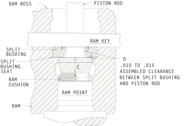 Using the boss on top of the Ram as a reference point, place a precision ground bar across the center hole of the Ram. Using a depth micrometer, measure the distance from the underside of the precision ground bar to the Split Bushing Seat, Letter A. Then measure the distance from the underside of the Precision Ground Bar to the top surface of the Ram Cushion, Letter B. The difference between these two dimensions is the distance between the Split Bushing seat and the top of the Ram Cushion- This distance should be .010″ to .015″ greater than the thickness of the flange at the lower end of the Piston Rod indicated by Letter C. If it is necessary to increase this distance, or measurement, remove the Ram Cushion from the Ram and reduce its thickness by lathe turning to the required dimension. If it is necessary to diminish this distance, or measurement, place a steel shim of correct thickness underneath the Ram Cushion on the top surface of the Ram Point. When the Ram Keys are driven securely into place, the Split Bushing will be clamped tightly against its Seat inside the Ram. With the Split Bushing thoroughly clamped in place against its seat, the Piston Rod must be free to move laterally. This lateral movement is allowed by the clearances provided by this installation method. Lateral movement clearances are allowed for at points indicated by Letter D.
Note: This procedure is also good for the Vulcan 520, 530, 535, 5110, 5150 and 6300 hammers. The tip was intended for offshore hammers, but it is also good for onshore hammers of these sizes. The ram key arrangement for smaller hammers is shown in Onshore Tip 18.
TIP # 051 : SHEET PILE DESIGNATIONS
To simplify Sheet Pile Designations for domestic manufacturers, there has been formulated a "New Standard, Designation" system. Given in the table below are the new and old designations for reference purposes. NEW STANDARD DESIGNATION U.S...
Read More
Tip #051: SHEET PILE DESIGNATIONS
To simplify Sheet Pile Designations for domestic manufacturers, there has been formulated a “New Standard, Designation” system. Given in the table below are the new and old designations for reference purposes.
| NEW STANDARD DESIGNATION |
U.S. ARMY CORPS OF ENGR. DESIGNATION |
U.S. STEEL |
BETHLEHEM |
WEIRTON STEEL (DlV. OF NAT’L.) |
AREA SQUARE INCHES |
LB. PER LINEAR FT. |
| PZ38 |
238 |
MZ38 |
ZP38 |
|
16.77 |
57 |
| PZ32 |
232 |
MZ32 |
ZP32 |
|
16.47 |
56 |
| PZ27 |
227 |
MZ27 |
ZP27 |
|
11.91 |
40.5 |
| PDA27 |
DA27 |
MP116 |
DP2 |
|
10.59 |
36 |
| PMA22 |
MA22 |
MP115 |
AP3 |
|
10.59 |
36 |
| PSA23 |
SA23 |
MP112 |
SP4 |
WS3 |
8.99 |
30.7 |
| PSA28 |
SA28 |
MP113 |
SP5 |
WS4 |
10.98 |
37.3 |
| PS28 |
S28 |
MP101 |
SRA |
WS1 |
10.29 |
35 |
| PS32 |
S32 |
MP102 |
SP7A |
WS2 |
11.76 |
40 |
| PSX35 |
|
MP103 |
SP7B |
|
13.09 |
44.5 |
|
|
|
|
WZ27 (not comp. PZ27) |
19 |
36 |
|
|
|
|
PWZ22 |
11.03 |
29.33 |
When ordering Helmets for driving steel sheet piling, please use the New Standard Designations.
Note: more information on older sheet piling sections can be found in the Vulcan Hammer Guide to Pile Driving Equipment.
TIP # 052 : KEYS TO CABLES
Factory Advertisement for conversion from keyed hammers to cables; not available online...
Read More
Tip #052: KEYS TO CABLES
Factory Advertisement for conversion from keyed hammers to cables; not available online.
TIP # 053 : SERIAL NUMBERS
It is frequently desirable to ascertain the age of equipment for appraisal, evaluation and a variety of other reasons. As is customary in most construction equipment, we show below the year of manufacture and the serial number range for that particul...
Read More
Tip #053: SERIAL NUMBERS
It is frequently desirable to ascertain the age of equipment for appraisal, evaluation and a variety of other reasons. As is customary in most construction equipment, we show below the year of manufacture and the serial number range for that particular year. As we approach one hundred years of serial numbers, we will on a yearly basis update this information.
| YEAR |
S/N RANGE |
YEAR |
S/N RANGE |
YEAR |
S/N RANGE |
YEAR |
S/N RANGE |
| 1888 |
1/7 |
1913 |
771/832 |
1938 |
2504/2546 |
1963 |
48569/48667 |
| 1889 |
8/13 |
1914 |
833/912 |
1939 |
2547/2586 |
1964 |
48668/48777 |
| 1890 |
14/36 |
1915 |
913/994 |
1940 |
2587/2671 |
1965 |
48778/48855
FE665/FE1290 |
| 1891 |
37/45 |
1916 |
995/1041 |
1941 |
2672/2806 |
1966 |
FF1295/FF3050 |
| 1892 |
46/60 |
1917 |
1042/1115 |
1942 |
2807/2902 |
1967 |
FG3055/FG5475 |
| 1893 |
61/73 |
1918 |
1116/1197 |
1943 |
2903/2970 |
1968 |
FH5480/FH6000 |
| 1894 |
74/86 |
1919 |
1198/1231 |
1944 |
2971/3157 |
1969 |
FI6005/FI6555 |
| 1895 |
87/98 |
1920 |
1232/1259 |
1945 |
3158/3199 |
1970 |
FJ6700/FJ6755
GJ6760/GJ7175 |
| 1896 |
99/110 |
1921 |
1260/1321 |
1946 |
3200/3259 |
1971 |
GA7185/GA7670 |
| 1897 |
111/124 |
1922 |
1322/1374 |
1947 |
3260/3328 |
1972 |
GB7675/GB8200 |
| 1898 |
125 |
1923 |
1375/1431 |
1948 |
3329/3404 |
1973 |
GC8205/GC8690 |
| 1899 |
126/148 |
1924 |
1432/1517 |
1949 |
3405/3464 |
1974 |
GD8695/GD9270 |
| 1900 |
149/157 |
1925 |
1518/1591 |
1950 |
3465/3571 |
1975 |
GE9275/GE9720 |
| 1901 |
158/194 |
1926 |
1592/1665 |
1951 |
3572/3663 |
1976 |
GF100/GF470 |
| 1902 |
195/231 |
1927 |
1666/1777 |
1952 |
3664/3747 |
1977 |
See Note Below |
| 1903 |
232/241 |
1928 |
1778/1906 |
1953 |
3748/3826 |
1978 |
| 1904 |
242/287 |
1929 |
1907/2039 |
1954 |
3827/3898 |
1979 |
| 1905 |
288/352 |
1930 |
2040/2164 |
1955 |
3899/4012 |
1980 |
| 1906 |
353/411 |
1931 |
2165/2258 |
1956 |
4013/4214 |
1981 |
| 1907 |
412/461 |
1932 |
2259/2300 |
1957 |
4215/4363 |
1982 |
| 1908 |
462/507 |
1933 |
2301/2324 |
1958 |
4364/4488 |
1983 |
| 1909 |
508/548 |
1934 |
2325/2364 |
1959 |
4489/4623 |
1984 |
| 1910 |
549/604 |
1935 |
2365/2379 |
1960 |
4624/4747 |
1985 |
| 1911 |
605/690 |
1936 |
2380/2450 |
1961 |
4748/48335 |
1986 |
| 1912 |
691/770 |
1937 |
2451/2503 |
1962 |
48336/48568 |
1987 |
Note: This tip, issued in 1976, was never followed up on; there were never any updates for the offshore tips (there was one in 1977 for the onshore ones; the information from that one is included above.) In fact, by the 1980’s Vulcan took this tip out of its distribution list in fear of people knowing the number of Vulcan hammers outstanding.
However, such updates were, in reality, unnecessary, because in 1965 Vulcan adopted its present system of serial numbers for hammers. This system gave the year of the hammer’s manufacture without having to consult the factory. All of this type of serial number is in the format of
XX-YYYY
where “XX” represents the year code in two letters; they translate into the last two digits of the year as shown in the table on the left. Thus, for a hammer with the serial number prefix “GF” this translates into “76”, thus the hammer was made in 1976. The implementation of these numbers can be seen above.
If you would like more information on this subject, or on a specific hammer serial number, you can fill out the form below and submit it.
Below is the list of hammers for Serial Number 48 through 971, for hammers in the years 1892-1915. (That includes S/N 463.
TIP # 054 : PRODUCT BULLETIN
Annually we publish a listing of all products currently in production. Listed below are all units in current production accompanied by current model and specification numbers. Note: This system was devised in order to bring some order to the desig...
Read More
Tip # 054 : PRODUCT BULLETIN
 Annually we publish a listing of all products currently in production. Listed below are all units in current production accompanied by current model and specification numbers.
Note: This system was devised in order to bring some order to the designation of Vulcan hammers. It was effectively dropped in the late 1970’s.
TIP # 055 : STEAM CHEST VALVE LINERS
Replaceable Steam Chest Valve Liners are standard equipment in all Vulcan Single and Differential Acting Pile Hammers These Valve Liners were adopted to provide easy means of replacing worn surfaces in the Steam Chest in lieu of reboring...
Read More
TIP # 055 : STEAM CHEST VALVE LINERS
Replaceable Steam Chest Valve Liners are standard equipment in all Vulcan Single and Differential Acting Pile Hammers These Valve Liners were adopted to provide easy means of replacing worn surfaces in the Steam Chest in lieu of reboring.
Given below in the table are the Serial Numbers and dates of the first hammer in each size to be equipped with Valve Liners. All hammers with Serial Numbers subsequent to those given for each size of Hammer are equipped with Valve Liners.
As changes take place. additional data will be provided.
| Hammer Size |
Serial Number & Date
|
| Onshore Std. |
Onshore Cable |
Offshore (Raised Steam Chest) |
Offshore (Lowered Steam Chest) |
| #2 |
FG-5335/11-29-67 |
|
|
|
| #1 |
FG-5280/10-23-67 |
|
|
|
| 06 |
FG-5465/12-21-67 |
|
|
|
| 106 |
FI-6180/4-21-69 |
|
|
|
| 08 |
FG-5205/9-11-67 |
GD-9200/12-4-74 |
|
|
| 010 |
FG-5240/9-27-67 |
GD9035/8-8-74 |
|
FJ-6700/6-26-70 |
| 014 |
FG-5345/12-16-67 |
|
|
|
| 016 |
FI-6335/7-15-69 |
|
|
FG-4075/4-4-67 |
| 020 |
FG-5190/8-19-67 |
|
|
FH-5530/2-24-68 |
| 030 |
|
|
|
FH-5645/4-19-68 |
| 040 |
|
FI-6240/5-8-69 |
|
FG-5330/12-8-67 |
| 340 |
|
|
|
GC-8245/2-12-73 |
| 540 |
|
|
|
GD-8800/5-22-74 |
| 060 |
|
|
|
FH-5555/6-15-68 |
| 360 |
|
|
|
GD-9025/7-19-74 |
| 560 |
|
|
|
GC-8445/7-18-73 |
| 3100 |
|
|
|
GE-9450/6-11-75 |
| 30C |
FH-5520/2-12-68 |
|
|
|
| 50C |
FG-5150/9-22-67 |
FH-5805/8-15-68 |
|
|
| 65C |
FG-5300/11-2-67 |
|
|
|
| 80C |
FG-4040/2-17-67 |
|
|
|
| 85C |
FI-6100/1-7-69 |
|
|
|
| 100C |
GA-7590/11-12-71 |
|
|
|
| 140C |
FF-3005/1-20-67 |
|
|
|
| 200C |
FH-5570/3-8-68 |
|
GA-7595/11-11-71 |
|
Note: This was never followed up on. But in reality there was no need to, as virtually any Vulcan hammer made after 1970 (those with a serial number starting with a “G”, “H” or “I”) had a valve liner. In addition to providing a replaceable wear surface, the valve liner eliminated the need to cut the valve stems custom for each hammer by providing a consistent location for the ports.
Vulcan’s serial number system is explained in Offshore Tip No. 016
TIP # 056 : VARI-CYCLE HAMMERS
Vulcan Vari-Cycle (Stroke Control) is available for all Vulcan Single Acting Hammers having a cylinder which has as an integrally cast pad part thereof the necessary mounting pads for installation of the Vari-Cycle equipment. Shown in the table below ...
Read More
TIP # 056 : VARI-CYCLE HAMMERS
Vulcan Vari-Cycle (Stroke Control) is available for all Vulcan Single Acting Hammers having a cylinder which has as an integrally cast pad part thereof the necessary mounting pads for installation of the Vari-Cycle equipment. Shown in the table below are the first Serial Number and date of those hammers (by size) having Vari-Cycle factory installed or mounting pads for field retrofit.
| Hammer Size |
Serial Numbers and Date |
| Onshore Hammers |
Offshore Hammers |
| #1 |
See Note 1 |
– |
| 06 |
See Note 2 |
– |
| 08 |
GB-8095/10-27-72 |
– |
| 010 |
GB-8100/11-2-72 |
– |
| 014 |
FI-6250/5-13-69 |
– |
| 016 |
FI-6515/12-19-69 |
FH-5500/2-1-68 |
| 020 |
FG-5190/12-19-69 |
FH-5530/2-15-68 |
| 030 |
– |
FH-5645/4-19-68 |
| 040 |
– |
FG-5330/12-8-67 |
| 340 |
– |
GC-8245/2-12-73 |
| 540 |
– |
GD-8800/5-22-74 |
| 060 |
– |
FH-5555/6-15-68 |
| 360 |
– |
GD-9025/7-19-74 |
| 560 |
– |
GC-8445/7-18-73 |
| 3100 |
– |
GE-9450/6-11-75 |
All Hammers having Serial Numbers subsequent to those above are configured as to accommodate Vari-Cycle.
Note 1 — The following Size #1 Hammers are equipped with mounting pads for Vari-Cycle:
GC-8455/GC-8555/GC-8595/GC-8715/GC-8765
Vari-Cycle mounting pads on this size Hammer were discontinued 8-23-74.
Note 2 — The following Size 06 Hammers are equipped with mounting pads for Vari-Cycle:
GD-8750/GD-8740/GD-8825/GD-8605/GC-8605/GC-8685
Van-Cycle mounting pads on this size Hammer were discontinued 7-24-74
Note: This tip obviously does not cover the hammers later than the mid-1970’s, especially the onshore 5′ stroke hammers. Their situation is complicated; you can contact us to ask questions about this. All of the Vulcan 5100, 5110, 5150 and 6300 hammers can accommodate Vari-Cycle and indeed virtually all offshore hammers from the 1970’s onward were either equipped with Vari-Cycle or Traverse Trip.
TIP # 057 : SERIAL NUMBERS
Vulcan Vari-Cycle (Stroke Control) is available for all Vulcan Single Acting Hammers having a cylinder which has as an integrally cast pad part thereof the necessary mounting pads for installation of the Vari-Cycle equipment. Shown in the table below ...
Read More
Tip # 057 : SERIAL NUMBERS
Vulcan Vari-Cycle (Stroke Control) is available for all Vulcan Single Acting Hammers having a cylinder which has as an integrally cast pad part thereof the necessary mounting pads for installation of the Vari-Cycle equipment. Shown in the table below are the first Serial Number and date of those hammers (by size) having Vari-Cycle factory installed or mounting pads for field retrofit.
| Hammer Size |
Serial Numbers and Date |
| Onshore Hammers |
Offshore Hammers |
| #1 |
See Note 1 |
– |
| 06 |
See Note 2 |
– |
| 08 |
GB-8095/10-27-72 |
– |
| 010 |
GB-8100/11-2-72 |
– |
| 014 |
FI-6250/5-13-69 |
– |
| 016 |
FI-6515/12-19-69 |
FH-5500/2-1-68 |
| 020 |
FG-5190/12-19-69 |
FH-5530/2-15-68 |
| 030 |
– |
FH-5645/4-19-68 |
| 040 |
– |
FG-5330/12-8-67 |
| 340 |
– |
GC-8245/2-12-73 |
| 540 |
– |
GD-8800/5-22-74 |
| 060 |
– |
FH-5555/6-15-68 |
| 360 |
– |
GD-9025/7-19-74 |
| 560 |
– |
GC-8445/7-18-73 |
| 3100 |
– |
GE-9450/6-11-75 |
All Hammers having Serial Numbers subsequent to those above are configured as to accommodate Vari-Cycle.
Note 1 — The following Size #1 Hammers are equipped with mounting pads for Vari-Cycle:
GC-8455/GC-8555/GC-8595/GC-8715/GC-8765
Vari-Cycle mounting pads on this size Hammer were discontinued 8-23-74.
Note 2 — The following Size 06 Hammers are equipped with mounting pads for Vari-Cycle:
GD-8750/GD-8740/GD-8825/GD-8605/GC-8605/GC-8685
Van-Cycle mounting pads on this size Hammer were discontinued 7-24-74
Note: This tip obviously does not cover the hammers later than the mid-1970’s, especially the onshore 5′ stroke hammers. Their situation is complicated; you can contact us to ask questions about this. All of the Vulcan 5100, 5110, 5150 and 6300 hammers can accommodate Vari-Cycle and indeed virtually all offshore hammers from the 1970’s onward were either equipped with Vari-Cycle or Traverse Trip.
TIP # 058 : NYLON SLIDE BARS
All Vulcan Air Steam Hammers currently sold have as standard slide bars made from a tough nylon to resist the whipping that a slide bar goes through in hammer cycling. In order to insure ...
Read More
Tip # 058 : NYLON SLIDE BARS
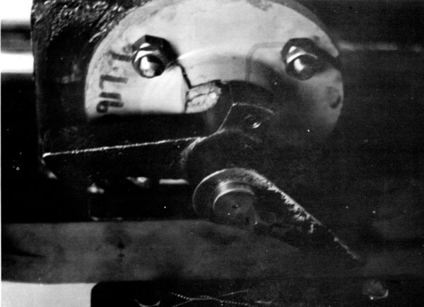 All Vulcan Air Steam Hammers currently sold have as standard slide bars made from a tough nylon to resist the whipping that a slide bar goes through in hammer cycling. In order to insure your nylon slide bar the longest possible life, we recommend the following procedures when using nylon slide bars:
- When using a nylon slide bar or installing one in an old hammer for the first time, make sure the trip is not excessively worn or has a large number of burrs on it. If either is the case, replace the trip.
- Make sure the hammer is sufficiently oiled through the air line. Although this is always important in hammer operation, it is especially so with nylon slide bars, since inadequate lubrication will cause the valve to drag and the trip feet to dig into the slide bar, thus ruining it.
- Unlubricated nylon slide bars will frequently squeal. To prevent this coat the slide bar with NLGl EP2 grease. This is also a good idea on the back and sides of the slide bar for lubrication of the dovetail.
TIP # 059 : CUSHION POT DIMENSIONS
Frequently in the course of designing a foundation, the dimensions of the cushion block are necessary for purposes of computing its stiffness for the wave equation analysis. Below are the cushion pot dimensions for our air/steam hammers...
Read More
Tip # 059 : CUSHION POT DIMENSIONS
Frequently in the course of designing a foundation, the dimensions of the cushion block are necessary for purposes of computing its stiffness for the wave equation analysis. Below are the cushion pot dimensions for our air/steam hammers:
| Hammer |
A |
B |
C |
D |
E |
F |
| 2, 30C |
10 1/4 |
7 |
1 1/2 |
– |
– |
– |
| 1, 06, 50C, 65C, 505, 506, 106 |
11 1/4 |
7 3/8 |
1 1/2 |
3 |
18 1/2 |
3 |
| 0, 08, 0R, 010, 010 Offshore, 012, 508, 510, 512, 65CA, 80C, 85C, 100C |
13 3/4 |
8 1/2 |
2 |
3 |
18 1/2 |
3 |
| 014, 016, 140C |
17 1/4 |
7 |
2 |
4 |
18 1/2 |
4 |
| 020 Onshore, 030 Onshore, 200C Onshore |
19 1/2 |
7 |
2 |
6 3/4 |
25 |
5 |
| 020 Offshore, 030 Offshore, 520, 530, 535, 200COffshore |
22 1/2 |
5 |
4 |
6 1/4 |
25 |
5 |
| 040, 340 |
25 1/4 |
9 1/2 |
4 |
12 1/4 |
26 1/2 |
5 |
| 060, 360 |
27 1/4 |
6 1/2 |
6 |
12 1/2 |
31 |
6 |
| 540 |
27 1/4 |
7 1/2 |
6 |
12 1/2 |
25 |
6 |
| 560, 5110 |
31 1/4 |
7 1/2 |
6 |
12 1/2 |
31 |
6 |
| 3100 |
36 1/4 |
7 1/2 |
6 |
12 1/2 |
25 |
6 |
| 5100 |
41 1/4 |
7 1/2 |
6 |
6 |
40 |
3 |
| 5150 |
45 1/4 |
9 1/2 |
6 |
6 |
40 |
3 |
| 4250 |
66 |
10 1/2 |
8 |
– |
– |
– |
| 6300 |
71 1/4 |
10 1/2 |
8 |
– |
– |
– |
Standard Pot
(Integral Ring)
Cap Block Follower
All dimensions in inches.
Note: Tip date 1 August 1980. Hammers and accessory dimensions have been added to the list to include onshore hammers and offshore hammers developed after that date. All additions are shown in italics.
TIP # 060 : HAMMER WARRANTY AND SAFETY
Frequently in the course of designing a foundation, the dimensions of the cushion block are necessary for purposes of computing its stiffness for the wave equation analysis. Below are the cushion pot dimensions for our air/steam hammers...
Read More
Tip # 060 : HAMMER WARRANTY AND SAFETY
 Listed to the left is our warranty, which is applied to all of our hammers that we sell. Among questions that come up relating to that warranty concerns the meaning of the phrase “operation beyond rated capacity.” Although not meant to be an all-inclusive list, the following are some of the criteria which constitute operation beyond the hammer’s rated capacity:
- Operation of the hammer at pile refusals of 120 blows per foot or above. This is true for all of our onshore hammers.
- Operation of the hammer with insufficient or excessively hard cushion material. The standard cushion thicknesses are given in Tip No. 59; these should be adhered to as closely to as possible. Excessively hard material can be caused by (a) material which is naturally too hard (such as either steel or micarta and aluminum in astandard pot) or (b) material which has become so in the course of driving. Determining whether the latter is true depends on the type of material being used, and the characteristics of the material should be observed with driving experience.
- Overstroking the hammer with excessive steam or air pressure. This produces both excessive ram point stresses and lifting and boucing of the hammer frame.
SAFETY TIPS
In orders to assist the users of Vulcan pile hammers with the safe operation of their driving equipment, Vulcan lron Works has issued the User’s Guide to Safe Operation. Following the recommendations of the manual will reduce the number of hammer associated accidents and the expense therefrom. Additional copies may be obtained without charge from Vulcan lron Works Inc.
 Note: this tip is obviously very “factory” oriented, and the references to the factory, Vulcan and its warranty are obviously of no present effect. It is useful, however, in two respects:
- It shows Vulcan’s opinion of the proper refusal criteria for its hammers, which can (or should at least) be significant in determining refusal criteria for specific jobs and piles.
- It represented the release of the User’s Guide to Safe Operation. The material in this booklet can be obtained in the Vulcan Hammer Guide to Pile Driving Equipment.
TIP # 061 : STUB CHANNEL MODIFICATION
Many of our customers, as a result of the stub channel design on new cable type hammers, have found the stub channels to be much more maintenance free. This modification can be made to older Vulcan hammers which were originally equipped with full...
Read More
Tip # 061 : STUB CHANNEL MODIFICATION
Many of our customers, as a result of the stub channel design on new cable type hammers, have found the stub channels to be much more maintenance free.
This modification can be made to older Vulcan hammers which were originally equipped with full length channels.
Should you desire to make this modification to you Vulcan hammer, contact the authorized represerrtative sefving your area or our factory for full details.
Note: as the tip implies, all Vulcan onshore hammers from the late 1970’s onwards had stub channels. The main disadvantage to stub channels is that it is more difficult to drive piling past the bottom of the leaders using them, and that problem is best addressed by the use of an extension. Extensions are described in the Vulcan Hammer Guide to Pile Driving Equipment.
TIP # 062 : EQUIPMENT HANDLING
While Pile Hammers are not unduly difficult to handle there are some basic precautions to be observed as well as some basic Do's and Don'ts. Note: Hammer handing as "not unduly difficult" only applies to specialists in material handing...
Read More
Tip # 062 : EQUIPMENT HANDLING
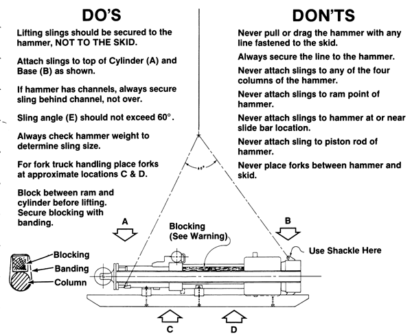 While Pile Hammers are not unduly difficult to handle there are some basic precautions to be observed as well as some basic Do’s and Don’ts.
Note: Hammer handing as “not unduly difficult” only applies to specialists in material handing.
TIP # 063 : ICING CONDITIONS
Operation of Pile Hammers and Pile Extractors on compressed air frequently presents problems of ice accumulation in valve assemblies and air passage ports. Icing is a function of temperature and humidity causing erratic equipment operation...
Read More
Tip # 063 : ICING CONDITIONS
 Operation of Pile Hammers and Pile Extractors on compressed air frequently presents problems of ice accumulation in valve assemblies and air passage ports. Icing is a function of temperature and humidity causing erratic equipment operation as, strange as it may seem, icing conditions occur at 85° as well as 32° if conditions are right.
There are several remedies for this problem which will help eliminate the icing condition:
- In your air line oiler, dilute your Iubricating oil with an equal amount of ethylene glycol.
- Install in the air line between the Lubricator and the Hammer a Tanner De-lcer Tank. The Tanner De-lcer atomizes the anti-icing chemical into the airstream to prevent Hammer icing. Tanner gas equipment is available from Tanner Systems, Inc., Sauk Rapids, Minnesota 56379.
Always remember that in subfreezing weather it is essential to preheat the Hammer Cylinder prior to commencing daily operation. This is necessary to eliminate any frozen condensate inside the Cylinder and Valve. It is also to prevent possible cracking of the Cylinder due to thermal shock. During winter operation, it is advisable to be sure that all condensate is expelled from the Lubricator at the end of the shift so that it will not be allowed to freeze thereby plugging the oil suction line. It is also advisable to preheat the Lubricator to assure immediate lubrication when operations are commenced.
TIP # 064 : PROPER HOSE CONNECTION
Before connecting air or steam hoses, check the outside of the hose to be sure it is in good, usable condition. Blow air or steam through the hose to be sure no dirt or debris is clogging the inside. Never use an air hose to carry steam...
Read More
Tip # 064 : PROPER HOSE CONNECTION
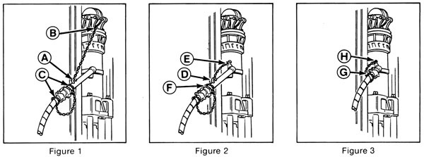
- Before connecting air or steam hoses, check the outside of the hose to be sure it is in good, usable condition.
- Blow air or steam through the hose to be sure no dirt or debris is clogging the inside.
- Never use an air hose to carry steam! Steam will melt the air hose. Take off all protective tape from the openings of the hammer cylinder.
- If the openings were not covered, check them to be sure they are clean. It is very important to keep hoses, couplings and openings free of dirt and debris. Doing this will add to the life and safety of the hammer.
- Air and steam hoses must be safely secured. If they are not, or if they come apart during use, the hoses will whip wildly over a great distance. This can be extremely dangerous and can cause substantial injuries to personnel and property. To lower the risks, all hoses and couplings should be checked at the beginning of each shift and after the driving of each pile.
- All hoses must be secured by a heavy chain or wire rope (refer to O.S.H.A. Standards 1926.251) attached to an anchor point on the hammer with a shackle, in a way that will support the weight of the hose at the coupling and help stop the jolting motions which happen during operation.
- There are several good ways of securing hoses:
- Figure 1 shows the method of running a chain or wire rope from the air/steam inlet extension (A) to the cylinder head bolts at the top of the hammer (6) and securing the air/steam coupling (C) with a separate chain or wire rope.
- Figure 2 shows the airisteam inlet extension (D) being connected to the lug (E) just above the air/steam inlet, which appears on some hammers, by a chain or wire rope and securing the air/steam coupling (F) with a separate chain or wire rope.
- Figure 3 shows the airlsteam coupling (G)a ttached directly to the air/steam inlet, without the use of an extension, and secured to lug (H) with a chain or wire rope.
TIP # 065 : SHEAVE ASSEMBLY CARE
Proper care of the sheave assembly is very important, since the weight of the hammer is held by this assembly and a flying sheave or falling hammer could strike a person causing severe injury. Sheaves, axles, pins, keys, nuts, and all lifting points...
Read More
TIP # 065 : SHEAVE ASSEMBLY CARE
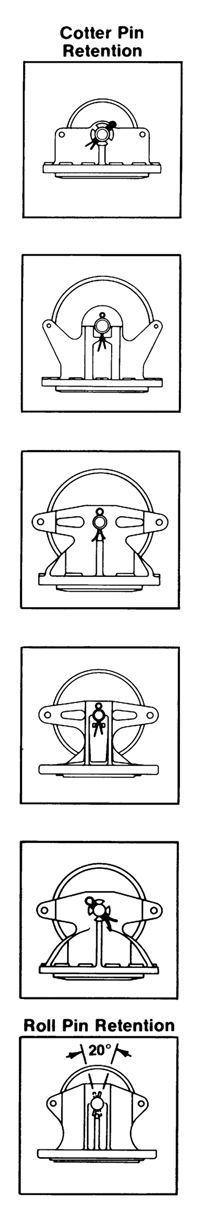 Proper care of the sheave assembly is very important, since the weight of the hammer is held by this assembly and a flying sheave or falling hammer could strike a person causing severe injury. Sheaves, axles, pins, keys, nuts, and all lifting points should be continuously checked for worn, loose or missing parts.
Check all cotter, roll and sheave pins for their condition and tightness and replace when worn or broken in service. Make sure that the correct type of pin (cotter or roll) is used with the corresponding type of head sheave. If in doubt, after examining the diagrams at left, consult an authorized dealer or the factory. The sheave pin is both held in place and kept from rotating by the two cotter (or roll) pins on each side.
If the sheave pin needs to be replaced, insert the new sheave pin with the sheave key in the existing hole until the key is firmly against the wall of the cylinder head. Then locate and drill a sheave key hole in the sheave pin. Make the hole the same size as the existing hole and locate it so that both sheave keys are pressed firmly against the walls of the cylinder head. Make sure that when cotter pins are installed the legs are spread so the cotter pin cannot fall out during service.
Roll pins use their internal tension to stay in place. The head sheave bushing should not be removed unless it needs replacement. Consult your Vulcan Onshore Field Service Manual for bushing replacement. If the head sheave needs replacement, a new bushing is included with the new sheave.
Always pull the hammer straight up, not at an angle to its central vertical axis. Pulling the hammer at an angle could pull the sheave pin through the head, disconnecting the hammer and sheave wheel causing both to fall. Avoid the use of spud or H-beam leaders with air-steam hammers of this type.
Use only genuine factory parts with this assembly, as with any other parts of the hammer. The use of nails, welding rod or re-bar to substitute for cotter or roll pins should be avoided
This is a very important safety bulletin and users of Vulcan hammers should take note and follow its recommendations seriously.
TIP # 066 : REDUCED HAMMER ENERGY
Vulcan Hammer Guide to Pile Driving Equipment...
Read More
TIP # 067 : LUBRICATION
Below are the lubrication specifications for the Vulcan offshore pile hammers. APPLICATION POINT Lube Type Oil Viscosity Flash Point (Min.) Other Requirements SUS, 212° F cSt, 100°C Deg. F Deg. C Cylinder and Base...
Read More
Tip # 067 : LUBRICATION
Below are the lubrication specifications for the Vulcan offshore pile hammers.
| APPLICATION POINT |
Lube Type |
Oil Viscosity |
Flash Point (Min.) |
Other Requirements |
| SUS, 212° F |
cSt, 100°C |
Deg. F |
Deg. C |
- Cylinder and Base Jaws.
- Trip Faces.
- Slide Bar.
- Slide Bar Dovetail.
- Columns/Ram Grease fittings*
- Columns/Exposed Surfaces*
- Hydra/Nuts
|
NLGI EP2 Grease |
70-100 |
13-20 |
450 |
235 |
- Permitted Thickners
- Lithium 12 Hydroxy-Stearate
- Lithium Complex
- Calcium Complex
- Polyurea
- MoS2 Anti-Wear Additive
- Anti-Rust Additive
|
- Relief Ports (Steam Opr.)
- Steam Line Oiler
|
Steam Cylinder Oil
AGMA 8 |
160-190 |
34-41 |
550 |
290 |
10% Tallow or Lard Content |
- Relief Ports (Air Opr.)
- Air Line Oiler
|
Air Compressor Oil
AGMA 1 |
40-50 |
40-50 |
400 |
200 |
Anti-Oxidant |
- Outboard Bearing
- Open Steam Chest Bearing
|
Gear Oil
AGMA 5 EP |
80-105 |
80-105 |
400 |
200 |
|
It is important to keep your Vulcan hammer properly lubricated to insure the maximum possible hammer life and driving performance.
Also, for the threads of the cable fittings. use an an anti-seize compound to prevent galIing and freezing of the threads.
*NLGI EP2 greases will vary widely in the results for this application. Another alternative to this is a heavy open gear lubricant with MoS2anti-wear additive. This should be applied directly to the exposed columns.
Lubrication Diagram
TIP # 068 : HAMMER BLOW RATE
Very frequently users and engineers make the assumption that the output energy of a hammer is somehow related to the number of blows per minute the hammer puts out. Such a notion is mistaken for both Single-Acting and Differential-Acting hammers...
Read More
Tip # 068 : HAMMER BLOW RATE
Very frequently users and engineers make the assumption that the output energy of a hammer is somehow related to the number of blows per minute the hammer puts out. Such a notion is mistaken for both Single-Acting and Differential-Acting hammers.
Vulcan specifications for blow rates are computed with the condition of “Normal Stroke, No Set.” This means first that the hammer must be getting a full stroke. This is the foremost method for Single-Acting hammers to determine sufficient energy and should be the main method to determine whether or not a hammer is performing properly.
With Differential-Acting hammers, the pressure at the hammer is the deciding factor. The second part of Vulcan blow rate specifications state that the blow rate is computed with no pile set considered. This includes both consideration of the time it takes to impact the pile and the effects of rebound on the hammer.
The interaction of the pile is an important component in determining the blow rate of a hammer and is extremely variable with driving conditions. Some hammers (such as the single-acting diesels) can have their energies estimated with their blow rates. Because of the action of the air supply, this cannot be done with Vulcan airlsteam hammers.
Users who need alternative methods to determine the energy output of the hammer should measure the ram velocity directly or use other accepted methods.
Note: this and Tip 9 deal with a subject that recurs with Vulcan hammers, and has been a source of confusion with some geotechnical engineers.
When Vulcan first introduced the Super Vulcan Differential-Acting hammers, it included with them a chart which correlated the blow rate of the hammer with the output energy. Unfortunately, this chart did not take into consideration either the time of impact or the rebound energy from the pile. Since Vulcan hammers (except for the diesel) were not designed to require rebound to acheive full stroke, the presence of initial velocity after impact seriously affected the blow rate and compromised the usefulness of the charts. Vulcan withdrew the charts and spent many years trying to live down their blowback.
The success of the diesel hammers–and the use of the Saximeter to estimte their rated energy–led some to attempt such a correlation with Vulcan single-acting air/steam hammers. Unfortunately no correlation can be established because of the different nature of the upstroke of these hammers and again because of rebound effects. But the result–confusion–remained.
Although a excessively slow hammer may indicate problems with binding or inadequate lubrication, there are many variables that go into a hammer’s actual blow rate in the field, and thus the factory wisely opted out of any further correlations between blow rate and energy for any of its hammers.
TIP # 069 : MICARTA AND ALUMINUM CUSHION MATERIAL
Micarta (or Conbest) and aluminum cushion material is an excellent cushion material for use in Vulcan AirISteam Impact Pile Hammers; however, the cushion pot configuration that can be used depends upon the hammer. Below is a breakdown of the various...
Read More
Tip # 069 : MICARTA AND ALUMINUM CUSHION MATERIAL
Hammers in which micarta and aluminum can be used in both integral ring and capblock follower cushion pots:
- #2
- #1
- 06
- 106
- #0
- 08
- 0R
- 010
- 012
- 014
- 016
|
Hammers in which micarta and aluminum can be used in the caplock follower only (integral ring use not recommended):
- 505
- 506
- 508
- 510
- 512
- 514
- 516
- 020
- 320
- 030
- 330
- 520
- 530
- 040
- 340
- 540
- 060
- 360
- 560
- 3100
- 5100
- 5150
- 5250
- 6300
- 30C
- 50C
- 65C
- 65CA
- 80C
- 85C
- 100C
- 140C
- 200C
|
This tip supersedes and replaces all previously released information on this subject.
TIP # 070 : HYDRAULIC CYLINDER TYPE PACKING UPGRADE (1 & 0)
For many years Vulcan hammers have used woven packing to seal around the piston rod. Although this type of packing has performed well, packing with longer life would obviously be better for hammer users. Vulcan now offers a packing that uses...
Read More
TIP # 070 : HYDRAULIC CYLINDER TYPE PACKING UPGRADE (1 & 0)
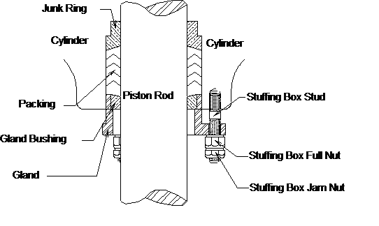 For many years Vulcan hammers have used woven packing to seal around the piston rod. Although this type of packing has performed well, packing with longer life would obviously be better for hammer users.
Vulcan now offers a packing that uses a chevron type packing, similar to rod packing used in hydraulic cylinders. This packing can be inserted into Vulcan hammers without modifying the hammers, providing the gland area of the cylinder is to original factory specifications.
This upgrade is available for Vulcan #1 series Hammers (#1, 06, 306 and 506 hammers, P/N 35366) or Vulcan #0 series hammers (#0, 0R, 08, 010, 012, 508, 510 and 512 hammers, P/N 6214C). This upgrade will work on Raymond and Conmaco hammers with the same cylinder packing gland as Vulcan’s.
Note: this was a rather late Vulcan adaptation of another Raymond innovation, namely the use of “Chevron” type packing in Vulcan hammers.
TIP # 071 : SERIAL NUMBERS (LETTER CODES)
It is frequently desirable to ascertain the age of equipment for appraisal, evaluation and a variety of other reasons. As is customary in most construction equipment, we show below the year of manufacture and the serial number range for that particul...
Read More
Tip # 071 : SERIAL NUMBERS (LETTER CODES)
It is frequently desirable to ascertain the age of equipment for appraisal, evaluation and a variety of other reasons. As is customary in most construction equipment, we show below the year of manufacture and the serial number range for that particular year. As we approach one hundred years of serial numbers, we will on a yearly basis update this information.
| YEAR |
S/N RANGE |
YEAR |
S/N RANGE |
YEAR |
S/N RANGE |
YEAR |
S/N RANGE |
| 1888 |
1/7 |
1913 |
771/832 |
1938 |
2504/2546 |
1963 |
48569/48667 |
| 1889 |
8/13 |
1914 |
833/912 |
1939 |
2547/2586 |
1964 |
48668/48777 |
| 1890 |
14/36 |
1915 |
913/994 |
1940 |
2587/2671 |
1965 |
48778/48855
FE665/FE1290 |
| 1891 |
37/45 |
1916 |
995/1041 |
1941 |
2672/2806 |
1966 |
FF1295/FF3050 |
| 1892 |
46/60 |
1917 |
1042/1115 |
1942 |
2807/2902 |
1967 |
FG3055/FG5475 |
| 1893 |
61/73 |
1918 |
1116/1197 |
1943 |
2903/2970 |
1968 |
FH5480/FH6000 |
| 1894 |
74/86 |
1919 |
1198/1231 |
1944 |
2971/3157 |
1969 |
FI6005/FI6555 |
| 1895 |
87/98 |
1920 |
1232/1259 |
1945 |
3158/3199 |
1970 |
FJ6700/FJ6755
GJ6760/GJ7175 |
| 1896 |
99/110 |
1921 |
1260/1321 |
1946 |
3200/3259 |
1971 |
GA7185/GA7670 |
| 1897 |
111/124 |
1922 |
1322/1374 |
1947 |
3260/3328 |
1972 |
GB7675/GB8200 |
| 1898 |
125 |
1923 |
1375/1431 |
1948 |
3329/3404 |
1973 |
GC8205/GC8690 |
| 1899 |
126/148 |
1924 |
1432/1517 |
1949 |
3405/3464 |
1974 |
GD8695/GD9270 |
| 1900 |
149/157 |
1925 |
1518/1591 |
1950 |
3465/3571 |
1975 |
GE9275/GE9720 |
| 1901 |
158/194 |
1926 |
1592/1665 |
1951 |
3572/3663 |
1976 |
GF100/GF470 |
| 1902 |
195/231 |
1927 |
1666/1777 |
1952 |
3664/3747 |
1977 |
See Note Below |
| 1903 |
232/241 |
1928 |
1778/1906 |
1953 |
3748/3826 |
1978 |
| 1904 |
242/287 |
1929 |
1907/2039 |
1954 |
3827/3898 |
1979 |
| 1905 |
288/352 |
1930 |
2040/2164 |
1955 |
3899/4012 |
1980 |
| 1906 |
353/411 |
1931 |
2165/2258 |
1956 |
4013/4214 |
1981 |
| 1907 |
412/461 |
1932 |
2259/2300 |
1957 |
4215/4363 |
1982 |
| 1908 |
462/507 |
1933 |
2301/2324 |
1958 |
4364/4488 |
1983 |
| 1909 |
508/548 |
1934 |
2325/2364 |
1959 |
4489/4623 |
1984 |
| 1910 |
549/604 |
1935 |
2365/2379 |
1960 |
4624/4747 |
1985 |
| 1911 |
605/690 |
1936 |
2380/2450 |
1961 |
4748/48335 |
1986 |
| 1912 |
691/770 |
1937 |
2451/2503 |
1962 |
48336/48568 |
1987 |
Note: This tip, issued in 1976, was never followed up on; there were never any updates for the offshore tips (there was one in 1977 for the onshore ones; the information from that one is included above.) In fact, by the 1980’s Vulcan took this tip out of its distribution list in fear of people knowing the number of Vulcan hammers outstanding.
However, such updates were, in reality, unnecessary, because in 1965 Vulcan adopted its present system of serial numbers for hammers. This system gave the year of the hammer’s manufacture without having to consult the factory. All of this type of serial number is in the format of
XX-YYYY
where “XX” represents the year code in two letters; they translate into the last two digits of the year as shown in the table on the left. Thus, for a hammer with the serial number prefix “GF” this translates into “76”, thus the hammer was made in 1976. The implementation of these numbers can be seen above.
If you would like more information on this subject, or on a specific hammer serial number, you can fill out the form below and submit it.
TIP # 072 : VARI-CYCLE II (506 & 512)
The Vulcan Vari-Cycle II offers all the advantages and ease of use of the original Vari-Cycle with fewer parts and less maintenance. When maintenance is required, it will be easier and less expensive. The Vari-Cycle II uses the same principle as ...
Read More
TIP # 072 : VARI-CYCLE II (506 & 512)
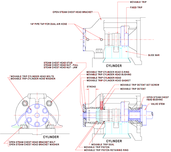 The Vulcan Vari-Cycle II offers all the advantages and ease of use of the original Vari-Cycle with fewer parts and less maintenance. When maintenance is required, it will be easier and less expensive. The Vari-Cycle II uses the same principle as the original Vari-Cycle, except the trip shifting cylinder is built into the Open Steam Chest Head Bracket thus reducing the number of parts. Air is supplied to the movable trip piston to move the trip into either the long stroke or short stroke position. A detent holds the trip in position when the air supply is removed. For the 306, 505 & 506 Hammers the Vari-Cycle II is P/N 13711. For the 508, 510 & 512 Hammers the Vari-Cycle II is P/N 13730. The Vari-Cycle II is designed to fit the above sizes of Hammers with a Traverse Trip or Vari-Cycle. On your next new Hammer specify Vari-Cycle II or contact Vulcan to see if your Hammer can be converted.
Note: this was Vulcan’s last Onshore Tip, issued by the Tennessee Corporation. The history behind it, however, isn’t one of Vulcan’s happier adventures.
Vulcan patented the Vari-Cycle–especially important with concrete piles for energy variation–in December 1967. Eleven years later Conmaco patented essentially the device you see above. When Vulcan discovered this device (shortly after Conmaco’s patent publication) and that it infringed on the Vulcan patent, it demanded that Conmaco desist from infringement. Conmaco countered by offering a cross-licensing agreement, allowing Vulcan to make and sell Conmaco’s enegy selector. Vulcan refused.
Conmaco did desist from infringement, but when Vulcan’s patent expired (1984) Conmaco was able to make their device without competition from Vulcan. By this time Vulcan began to market its 506 and 512 hammers, and the increased rebound loads from 5′ stroke driving gave the Vari-Cycle reliability problems on these hammers (the device in the larger hammers was more robust.) Adopting “Vari-Cycle II” would have solved this problem, but Vulcan was precluded from doing so until 1995, by which time Vulcan was headed towards merger.
This debacle was an illustration of a point made many years ago:
“Agree with thine adversary quickly, while thou art in the way with him…(Matthew 5:25)”
 One of the most successful information programs Vulcan ever conducted was the Vulcan Tips program. The first tip was issued in 1973. Although most of them were issued in the 1970’s, Vulcan issued Onshore Tips until the late 1990’s. They went beyond the Vulcan Data Manual in providing practical suggestions for proper operation of Vulcan hammers.